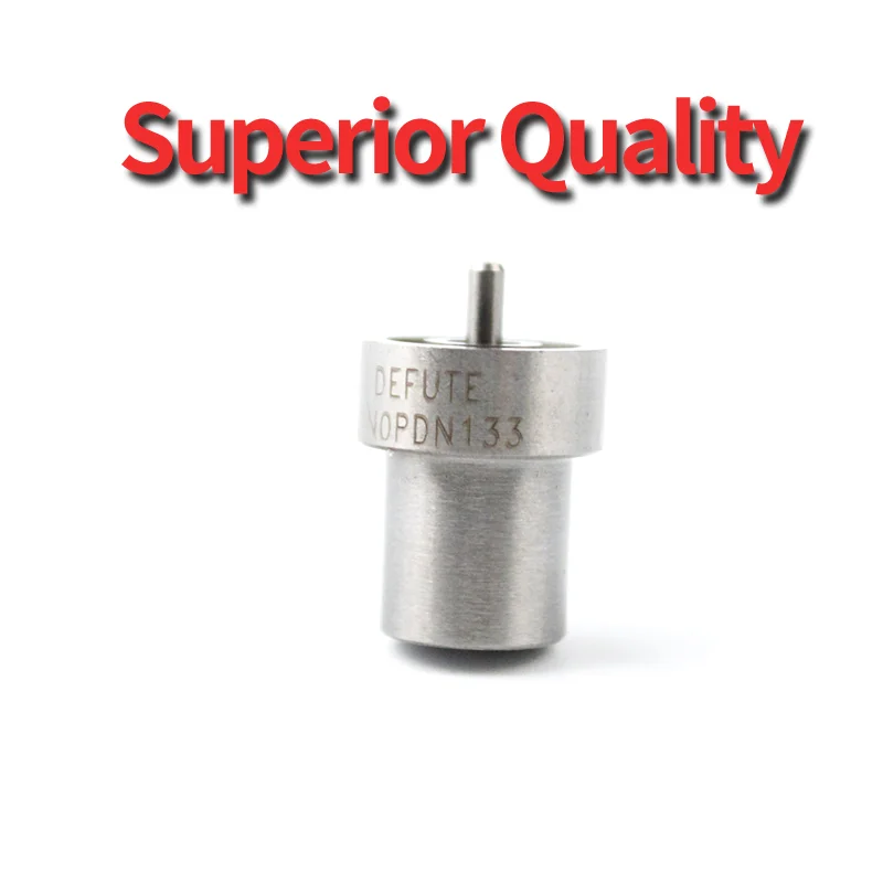
Information nozzle
BOSCH
9 432 610 327
9432610327
ZEXEL
105007-1330
1050071330
ISUZU
8971296440
8971296440

Rating:
Compare Prices: .
As an associate, we earn commssions on qualifying purchases through the links below

DNOPDNN133 Fuel Injector Nozzle 6 Pcs 105007-1330 Compatible With Zexel Compatible With 4JG2 Engine
Generic DNOPDNN133 Fuel Injector Nozzle 6 Pcs 105007-1330 Compatible With Zexel Compatible With 4JG2 Engine
Generic DNOPDNN133 Fuel Injector Nozzle 6 Pcs 105007-1330 Compatible With Zexel Compatible With 4JG2 Engine

DN0PDN128 DN4PD3 DN15PD6 DN0PD20 DN0PD121 DN0PD31 DN0PDN135 DN0PDN133 DN0PD874 DN10PDN129 Diesel Fuel Injection Nozzle(DN15PD6)
jianlibm Covers mainstream diesel powertrains || Wide compatibility: It supports 10 mainstream diesel fuel injector models such as DN0PDN128, DN4PD3, DN15PD6, etc., and is compatible with common rail systems of Bosch, Delphi and other brands || Cross-model versatility: compatible with commercial vehicles such as Mercedes-Benz, Volvo, and Scania, as well as engineering equipment such as Caterpillar and Komatsu || 2. Precision fuel injection technology to improve combustion efficiency and performance || Optimized nozzle design: multi-hole (e.g., 7-hole, 10-hole) layout, || High pressure adaptation: Match the high load conditions of turbocharged engines || 3. High-strength materials and processes, resistant to harsh working conditions || Wear-resistant and anti-corrosion: the needle valve is coated with tungsten carbide, and the valve body is made of stainless steel || Precision machining technology: the size tolerance of the nozzle hole is controlled within ±5μm || 4. Professional maintenance tool support, efficient disassembly and calibration
jianlibm Covers mainstream diesel powertrains || Wide compatibility: It supports 10 mainstream diesel fuel injector models such as DN0PDN128, DN4PD3, DN15PD6, etc., and is compatible with common rail systems of Bosch, Delphi and other brands || Cross-model versatility: compatible with commercial vehicles such as Mercedes-Benz, Volvo, and Scania, as well as engineering equipment such as Caterpillar and Komatsu || 2. Precision fuel injection technology to improve combustion efficiency and performance || Optimized nozzle design: multi-hole (e.g., 7-hole, 10-hole) layout, || High pressure adaptation: Match the high load conditions of turbocharged engines || 3. High-strength materials and processes, resistant to harsh working conditions || Wear-resistant and anti-corrosion: the needle valve is coated with tungsten carbide, and the valve body is made of stainless steel || Precision machining technology: the size tolerance of the nozzle hole is controlled within ±5μm || 4. Professional maintenance tool support, efficient disassembly and calibration

You can express buy:
USD 4.58
13-05-2025
13-05-2025
Diesel engine nozzle DN0PDN133 105007-1330 High quality electric fuel injection pump nozzle for PD series D0231
USD 4.58
13-05-2025
13-05-2025
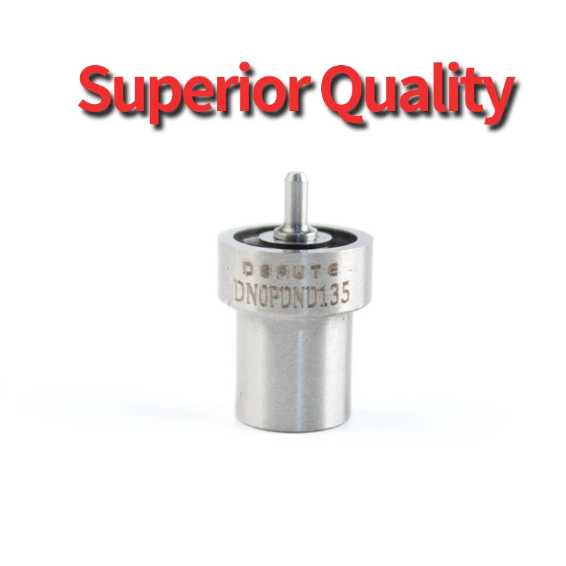
Diesel engine shaft needle injector DN0PDN135 105007-1330 Injector fittings Oil nozzle straight supply quality is stable D0231
USD 3.5
13-05-2025
13-05-2025
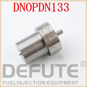
Diesel injector Nozzle DNOPDN133 / DN0PDN133 1050071330 sprayer nozzle DN0PDN133
Images:
USD 41.99

[28-Apr-2025]
USD 18

[11-Nov-2022]
USD 3.5

[20-Nov-2018]
USD 3.5

[20-Nov-2018]
Include in #2:
104134-3001
as NOZZLE
Cross reference number
Zexel num
Bosch num
Firm num
Name
Information:
start by: a) remove pistons1. Check to be sure all coolant has been removed from the cylinder block.2. Put protection over the crankshaft bearing journals before removing cylinder liners.3. Put location marks on the cylinder liners with respect to their location in block. 4. Use tool setup (A) to remove the cylinder liners from block.5. Remove the seals from cylinder liners.6. Use a straight blade scraper to loosen the spacer plate (1) from cylinder block.
Use care when loosening the plate from cylinder block or damage to plate may result.
7. Remove the spacer plate (1).Install Cylinder Liners
1. Thoroughly clean both sides of spacer plate and top surface of block. Install spacer plate gasket and spacer plate on the cylinder block.
Make sure both sides of plate and top of block are clean and dry before installing gasket and plate. Do not put gasket adhesives or any other substance on these surfaces.
2. Put the cylinder liners in their respective positions in cylinder block. Install tool setup (B) and two cylinder head bolts and washers. Tighten the bolts to 70 5 lb.ft. (9.7 0.7 mkg).3. Check the cylinder liner projection using tool setup (C) as follows: a) Install the four spacers from tool group and four cylinder head bolts and washers. Tighten bolts to 70 5 lb.ft. (9.7 0.7 mkg).b) Use dial indicator, block, and gauge from the tool group to check liner projection at four locations around the liner.c) Cylinder liner projection must be .0030 to .0076 in. (0.076 to 0.193 mm). Projection between liners next to each other must not be different by more than .001 in. (0.025 mm). 4. Remove tool setup (B) and (C). Remove the liners from cylinder block.5. Install the O-ring seals on bottom of liners. Put liquid soap on the seals.
TYPICAL EXAMPLE6. Put oil on the filler band seal, and install the seal on top end of liner. Install the cylinder liners immediately into their respective locations in cylinder block using tool (A).
Do not let the filler band seal stay in oil except for a very short time because the oil will make the seal much bigger very fast. After putting oil on the filler band seal, install the liner immediately into block.
end by: a) install pistons.