Information nozzle
BOSCH
9 432 610 295
9432610295
ZEXEL
105007-1300
1050071300
MITSUBISHI
ME731688
me731688

Rating:
Compare Prices: .
As an associate, we earn commssions on qualifying purchases through the links below

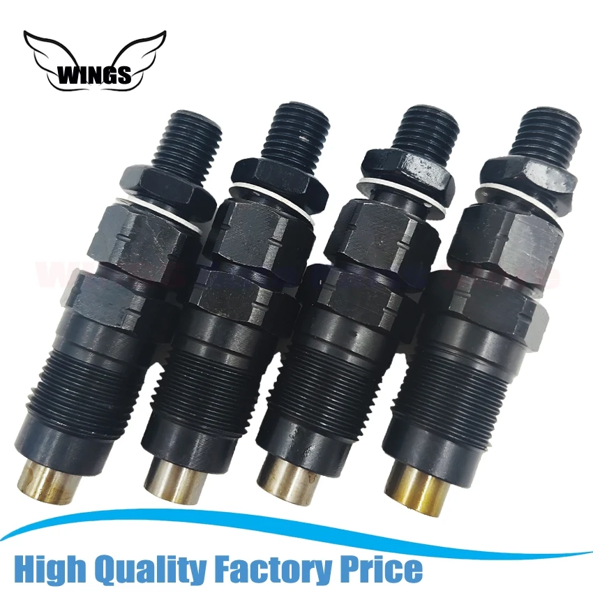
HYUERI DN10PDN130 Diesel Fuel Injector Nozzle Compatible with Mitsubishi L200 L300 Pajero Shogun Triton 4D56
HYUERI Make the fuel and air to achieve the best mixing ratio, improve combustion efficiency, to ensure that the engine can maintain good performance under various working conditions. || Precise fuel injection helps the engine to fully burn fuel, which effectively improves the car's power performance and makes acceleration smoother and more powerful. || By precisely controlling the amount of fuel injection, the waste of fuel is avoided, the fuel is fully utilized, the fuel consumption is reduced, and the fuel cost is saved for the owner. || The fuel is fully atomized into fine particles, so that combustion is faster and more fully, and the thermal efficiency of the engine is improved. || It can quickly adjust the fuel injection amount and fuel injection time according to the engine working condition changes, so that the engine can quickly respond to the driver's operation, such as rapid acceleration, rapid deceleration and so on.
HYUERI Make the fuel and air to achieve the best mixing ratio, improve combustion efficiency, to ensure that the engine can maintain good performance under various working conditions. || Precise fuel injection helps the engine to fully burn fuel, which effectively improves the car's power performance and makes acceleration smoother and more powerful. || By precisely controlling the amount of fuel injection, the waste of fuel is avoided, the fuel is fully utilized, the fuel consumption is reduced, and the fuel cost is saved for the owner. || The fuel is fully atomized into fine particles, so that combustion is faster and more fully, and the thermal efficiency of the engine is improved. || It can quickly adjust the fuel injection amount and fuel injection time according to the engine working condition changes, so that the engine can quickly respond to the driver's operation, such as rapid acceleration, rapid deceleration and so on.

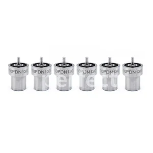
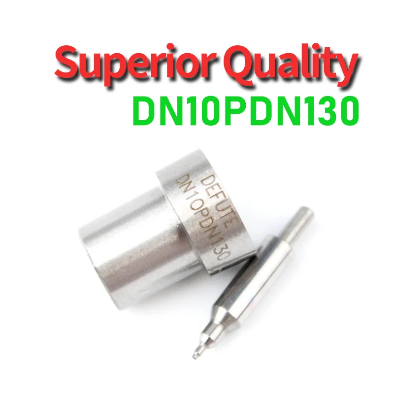
DN10PDN130 Diesel Fuel Injector Nozzle .Compatible For Mitsubishi L200 L300 Shogun Triton 4D56
Wvbdhd Stamping No: DN10PDN130 || Can accurately control the amount of fuel injected to improve combustion efficiency. || Atomizes the fuel into fine particles, increasing the area of the fuel and promoting full combustion. || Optimize fuel injection to make the engine burn more fully, thus improving the engine's power performance. || Precise fuel injection and good atomization make full use of fuel, reduce fuel consumption and save fuel costs.
Wvbdhd Stamping No: DN10PDN130 || Can accurately control the amount of fuel injected to improve combustion efficiency. || Atomizes the fuel into fine particles, increasing the area of the fuel and promoting full combustion. || Optimize fuel injection to make the engine burn more fully, thus improving the engine's power performance. || Precise fuel injection and good atomization make full use of fuel, reduce fuel consumption and save fuel costs.

MGHF 4pcs Diesel Fuel Injector Nozzle DN0PDN121 DN0PDN124 DN0PDN112 DN20PD32 DN0PD95 DN0PDN130 DN10PDN130 DN0PDN113 DN0PDN159 DN4PD62(DN0PDN130)
MGHF 【Quality Assurance】 - Highest quality materials are utilized along with stringent quality control standards to meet or exceed OE specifications. The O-Rings are made with heat resistant material to withstand extreme temperatures, the fuel Injectors undergo extensive lab and vehicle fitment testing。 || 【Fuel Economy】- The design of automobile fuel injectors can accurately control the amount of fuel injection, thereby optimizing fuel economy and helping you save fuel costs。 || 【Durability】- Our automotive fuel injectors are precision manufactured and subject to strict quality control, providing excellent durability and ensuring long-term and stable use。 || 【EASY TO INSTALL】Easy to remove and replace, very short installation time, reduce maintenance cost and time, fine workmanship and beautiful appearance。 || 【Regular Cleaning Fuel Injectors】- Generally speaking, if the car is in good condition and the fuel quality is good, it can be done every 40,000-60,000 kilometers. Even if the fuel injection nozzle is slightly clogged, you don't need to be too nervous, because the impurities can be sprayed and dissolved when accelerating at a high gear. It is recommended that car owners should often run at high speeds when driving daily to reduce the possibility of carbon deposits。
MGHF 【Quality Assurance】 - Highest quality materials are utilized along with stringent quality control standards to meet or exceed OE specifications. The O-Rings are made with heat resistant material to withstand extreme temperatures, the fuel Injectors undergo extensive lab and vehicle fitment testing。 || 【Fuel Economy】- The design of automobile fuel injectors can accurately control the amount of fuel injection, thereby optimizing fuel economy and helping you save fuel costs。 || 【Durability】- Our automotive fuel injectors are precision manufactured and subject to strict quality control, providing excellent durability and ensuring long-term and stable use。 || 【EASY TO INSTALL】Easy to remove and replace, very short installation time, reduce maintenance cost and time, fine workmanship and beautiful appearance。 || 【Regular Cleaning Fuel Injectors】- Generally speaking, if the car is in good condition and the fuel quality is good, it can be done every 40,000-60,000 kilometers. Even if the fuel injection nozzle is slightly clogged, you don't need to be too nervous, because the impurities can be sprayed and dissolved when accelerating at a high gear. It is recommended that car owners should often run at high speeds when driving daily to reduce the possibility of carbon deposits。
You can express buy:
USD 25.83
14-06-2025
14-06-2025
4PCS Engine Fuel Injector 105148-1311 MD196607 105007-1300 1051481310 for Mitsubishi 4D56 L400 L200 L300 Pajero K34T K74T P15V
USD 43.72
14-06-2025
14-06-2025
For Mitsubishi L200 L300 Pajero Shogun Triton 4D56 6pcsx Injector Nozzle DN10PDN130 105007-1300
USD 4.66
13-05-2025
13-05-2025
DN10PDN130 Diesel injector with 105007-1300 injector for Ruifeng 4D56T 2.5TD and modern injector D0331
Images:
USD 3.5

[13-May-2025]
USD 10.52

[25-Jun-2025]
USD 3.5

[12-Nov-2023]
USD 5.18

[19-Dec-2024]
Include in #2:
104700-3001
as NOZZLE
Cross reference number
Zexel num
Bosch num
Firm num
Name
Information:
2. Remove the four bolts (2) that hold flange to aftercooler cover. Loosen clamp (6) on the turbocharger, and turn housing until inlet pipe is away from camshaft housing.3. Remove the oil drain line for the turbocharger.4. Disconnect the wiring from the glow plugs.5. Remove the inner fuel injection lines (4).6. Disconnect the outer fuel injection lines from the camshaft housing.7. Disconnect the wiring (3) for the glow plugs from the camshaft housing.8. Remove lifting bracket (1) from housing. 9. Remove the two bolts (7), nuts (8), and locks.10. Remove the bolts (5) that hold the camshaft housing in position. 11. Fasten a hoist to the camshaft housing. Remove camshaft housing (9). Weight of housing is 100 lb. (45 kg).Install Camshaft Housing
1. Turn all adjustment screws counterclockwise as far as possible to get maximum valve lash. Turn the camshafts until the "V" timing marks on drive gears (2) and (3) are in alignment as shown. Install the timing pin in timing hole in camshaft housing.2. Check to be sure the No. 1 piston is at the "TOP CENTER COMPRESSION" position, and the timing bolt is installed in flywheel.
The procedure in Steps 1 and 2 must be followed or damage to the engine may result.
3. Fasten a hoist and put camshaft housing in position on engine with gear (3) engaged with gear (4) in cylinder head. Install the bolts (1), nuts, and locks that hold the camshaft housing in position. Install lifting bracket (5).4. Connect the fuel injection lines to outside of camshaft housing. Install inner lines. Tighten the nuts on lines to 30 5 lb.ft. (4.1 0.7 mkg).5. Remove the timing pin from camshaft housing and timing bolt from flywheel.6. Make the valve lash adjustment as follows: Make an adjustment to exhaust valves for cylinders 1-3-5 and inlet valves for cylinders 1-2-4. Turn the crankshaft 360° so No. 6 piston is at "TOP CENTER COMPRESSION" position. Make an adjustment to exhaust valves for cylinders 2-4-6 and inlet valves for cylinders 3-5-6.a) Turn screws clockwise until there is zero clearance between the button on screw and the valve.b) Turn screws counterclockwise four clicks to get .008 in. (0.2 mm) clearance for the inlet valves.c) Turn screws counterclockwise ten clicks to get .020 in. (0.5 mm) clearance for the exhaust valves.7. Connect the wiring for the glow plugs. Install the oil drain line for the turbocharger.8. Turn the housing to put pipe (6) into position, and install the four bolts. Tighten clamp (7).end by: a) install valve coverb) install alternatorDisassemble Camshaft Housing
start by: a) remove camshaft housing 1. Remove the four bolts (3) and lock from each drive gear. Remove the camshaft drive gears (1) and (2). 2. Remove the two bolts (5), lock, and plate (4) that hold camshafts in position. 3. Remove the inlet camshaft (6) and exhaust camshaft (7) from housing.4. Remove lifting bracket (8) from end of camshaft housing. 5. Remove the two bolts (11) that hold the rocker shafts in position.6. Remove the