Information injection-pump assembly
BOSCH
9 400 613 385
9400613385
ZEXEL
101609-3760
1016093760
KOMATSU
4063845
4063845

Rating:
Compare Prices: .
As an associate, we earn commssions on qualifying purchases through the links below

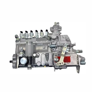
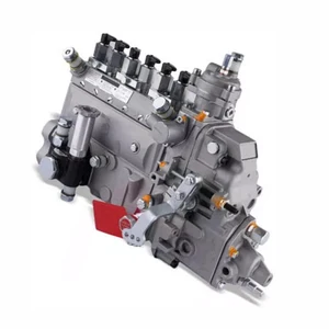
Car fuel pump assembly, Excavator PC220-7 6BT5.9 6D102 Fuel Injection Pump 6738-71-1520 4063844 4063845 101609-3750 101609-3760
ZTUVUNVA The design of the oil outlet is exquisite and reasonable, which avoids carbon deposition at the oil outlet and effectively prolongs the service life. || Reduce fuel consumption, improve jitter and accelerate smoothly. || The oil meter is accurate, which can solve the problems of abnormal oil consumption, misfire and no power. || Solve problems such as abnormal fuel meter data. || Sufficient oil return flow ensures stable pressure and sufficient cooling of the fuel system.
ZTUVUNVA The design of the oil outlet is exquisite and reasonable, which avoids carbon deposition at the oil outlet and effectively prolongs the service life. || Reduce fuel consumption, improve jitter and accelerate smoothly. || The oil meter is accurate, which can solve the problems of abnormal oil consumption, misfire and no power. || Solve problems such as abnormal fuel meter data. || Sufficient oil return flow ensures stable pressure and sufficient cooling of the fuel system.
Excavator PC220-7 6BT5.9 6D102 Fuel Injection Pump 6738-71-1520 4063844 4063845 101609-3750 101609-3760
JUCAQYZT 【 Upgraded Material 】: Made of high-performance alloy, suitable for various extreme weather conditions, resistant to high temperatures and cold winters. A good fuel injection pump is crucial for engine power, fuel efficiency, and fuel economy. || 【 Non destructive installation 】: The installation is very simple, without complex installation processes, easy to get started, and does not damage your car. || 【 Improving Fuel Economy 】: High precision manufacturing processes ensure the accuracy of fuel metering and injection, and the internal fuel flow channels have been optimized to reduce pressure loss, atomize fuel, and improve fuel efficiency and economy. || 【 More Stable Operation 】: The excellent design minimizes noise and vibration during operation, providing you with a quieter and more comfortable driving experience. || Excavator PC220-7 6BT5.9 6D102 Fuel Injection Pump 6738-71-1520 4063844 4063845 101609-3750 101609-3760
JUCAQYZT 【 Upgraded Material 】: Made of high-performance alloy, suitable for various extreme weather conditions, resistant to high temperatures and cold winters. A good fuel injection pump is crucial for engine power, fuel efficiency, and fuel economy. || 【 Non destructive installation 】: The installation is very simple, without complex installation processes, easy to get started, and does not damage your car. || 【 Improving Fuel Economy 】: High precision manufacturing processes ensure the accuracy of fuel metering and injection, and the internal fuel flow channels have been optimized to reduce pressure loss, atomize fuel, and improve fuel efficiency and economy. || 【 More Stable Operation 】: The excellent design minimizes noise and vibration during operation, providing you with a quieter and more comfortable driving experience. || Excavator PC220-7 6BT5.9 6D102 Fuel Injection Pump 6738-71-1520 4063844 4063845 101609-3750 101609-3760

Fuel Injection Pump 101609-3760 4063845 Compatible with Cummins 6BT for Komatsu PC200-6 PC220-6
Teaviatorial 🔥Part Name:Fuel Injection Pump || 🔥Part Number:101609-3760 4063845 || 🔥Application:6BT PC200-6 PC220-6 || 🔥Tip: If you need any other parts, please contact us - we are a professional sales team and have many products to offer to you. Many buyers are very satisfied with our service. You can get first-class products and high-quality services from us, believe me, you will have a pleasant shopping experience here. || 🔥Attention: If you are unsure if the product is suitable for your machine model. In order not to delay your use of the parts, please provide your engine nameplate or serial number and part number, and we will help you confirm if it is suitable. To avoid unnecessary returns, please carefully check the product image and part number to ensure that it is the product you want. Thank you for your support and understanding!
Teaviatorial 🔥Part Name:Fuel Injection Pump || 🔥Part Number:101609-3760 4063845 || 🔥Application:6BT PC200-6 PC220-6 || 🔥Tip: If you need any other parts, please contact us - we are a professional sales team and have many products to offer to you. Many buyers are very satisfied with our service. You can get first-class products and high-quality services from us, believe me, you will have a pleasant shopping experience here. || 🔥Attention: If you are unsure if the product is suitable for your machine model. In order not to delay your use of the parts, please provide your engine nameplate or serial number and part number, and we will help you confirm if it is suitable. To avoid unnecessary returns, please carefully check the product image and part number to ensure that it is the product you want. Thank you for your support and understanding!
You can express buy:
USD 1496.69
14-06-2025
14-06-2025
XCWoOshop 101609-3760 Fuel Injection Pump 4063845 Compatible with Cummins 6BT Komatsu PC200-6 PC220-6
USD 1514.77
19-05-2025
19-05-2025
XCWoOshop fuel pump 101609-3760 4063844 101609-3750 101600-3780 fit for PC220-7 6D102 6B 6BT 6BT5.9 B5.9 6B5.9 6BT59
Images:
USD 1373.97

[19-May-2025]
USD 2098.17

[14-Jun-2025]
USD 1400.79

[14-Jun-2025]
USD 2328.21

[19-May-2025]
Service parts 101609-3760 INJECTION-PUMP ASSEMBLY:
1.
_


5.
AUTOM. ADVANCE MECHANIS
6.
COUPLING PLATE
7.
COUPLING PLATE
8.
_
9.
_
11.
Nozzle and Holder
12.
Open Pre:MPa(Kqf/cm2)
22.0{240}

15.
NOZZLE SET
Include in #1:
101609-3760
as INJECTION-PUMP ASSEMBLY
Include in #2:
104268-1152
as _
Cross reference number
BOSCH
9 400 613 385
9400613385
ZEXEL
101609-3760
1016093760
KOMATSU
4063845
4063845
Zexel num
Bosch num
Firm num
Name
101609-3760
9 400 613 385
4063845 KOMATSU
INJECTION-PUMP ASSEMBLY
6BTAA K 14BE INJECTION PUMP ASSY PE6A PE
6BTAA K 14BE INJECTION PUMP ASSY PE6A PE
101609-3760
9 400 613 385
6738711530 KOMATSU
INJECTION-PUMP ASSEMBLY
6BTAA K 14BE INJECTION PUMP ASSY PE6A PE
6BTAA K 14BE INJECTION PUMP ASSY PE6A PE
Calibration Data:
Adjustment conditions
Test oil
1404 Test oil ISO4113 or {SAEJ967d}
1404 Test oil ISO4113 or {SAEJ967d}
Test oil temperature
degC
40
40
45
Nozzle and nozzle holder
105780-8140
Bosch type code
EF8511/9A
Nozzle
105780-0000
Bosch type code
DN12SD12T
Nozzle holder
105780-2080
Bosch type code
EF8511/9
Opening pressure
MPa
17.2
Opening pressure
kgf/cm2
175
Injection pipe
Outer diameter - inner diameter - length (mm) mm 6-2-600
Outer diameter - inner diameter - length (mm) mm 6-2-600
Overflow valve
131424-3420
Overflow valve opening pressure
kPa
255
221
289
Overflow valve opening pressure
kgf/cm2
2.6
2.25
2.95
Tester oil delivery pressure
kPa
255
255
255
Tester oil delivery pressure
kgf/cm2
2.6
2.6
2.6
Direction of rotation (viewed from drive side)
Right R
Right R
Injection timing adjustment
Direction of rotation (viewed from drive side)
Right R
Right R
Injection order
1-5-3-6-
2-4
Pre-stroke
mm
2.6
2.55
2.65
Rack position
After adjusting injection quantity. R=A
After adjusting injection quantity. R=A
Beginning of injection position
Drive side NO.1
Drive side NO.1
Difference between angles 1
Cal 1-5 deg. 60 59.5 60.5
Cal 1-5 deg. 60 59.5 60.5
Difference between angles 2
Cal 1-3 deg. 120 119.5 120.5
Cal 1-3 deg. 120 119.5 120.5
Difference between angles 3
Cal 1-6 deg. 180 179.5 180.5
Cal 1-6 deg. 180 179.5 180.5
Difference between angles 4
Cyl.1-2 deg. 240 239.5 240.5
Cyl.1-2 deg. 240 239.5 240.5
Difference between angles 5
Cal 1-4 deg. 300 299.5 300.5
Cal 1-4 deg. 300 299.5 300.5
Injection quantity adjustment
Adjusting point
A
Rack position
12
Pump speed
r/min
1000
1000
1000
Average injection quantity
mm3/st.
128.5
127.5
129.5
Max. variation between cylinders
%
0
-2.5
2.5
Basic
*
Fixing the lever
*
Boost pressure
kPa
53.3
53.3
Boost pressure
mmHg
400
400
Injection quantity adjustment_02
Adjusting point
-
Rack position
7.8+-0.5
Pump speed
r/min
525
525
525
Average injection quantity
mm3/st.
9.5
8.5
10.5
Max. variation between cylinders
%
0
-15
15
Fixing the rack
*
Boost pressure
kPa
0
0
0
Boost pressure
mmHg
0
0
0
Remarks
Adjust only variation between cylinders; adjust governor according to governor specifications.
Adjust only variation between cylinders; adjust governor according to governor specifications.
Injection quantity adjustment_03
Adjusting point
D
Rack position
10.3
Pump speed
r/min
100
100
100
Average injection quantity
mm3/st.
50
45
55
Fixing the lever
*
Boost pressure
kPa
53.3
53.3
Boost pressure
mmHg
400
400
Injection quantity adjustment_04
Adjusting point
E
Rack position
12.2++
Pump speed
r/min
100
100
100
Average injection quantity
mm3/st.
120
115
125
Fixing the lever
*
Boost pressure
kPa
53.3
53.3
Boost pressure
mmHg
400
400
Rack limit
*
Boost compensator adjustment
Pump speed
r/min
850
850
850
Rack position
10.3
Boost pressure
kPa
29.3
26.6
32
Boost pressure
mmHg
220
200
240
Boost compensator adjustment_02
Pump speed
r/min
850
850
850
Rack position
R1(12)
Boost pressure
kPa
40
40
40
Boost pressure
mmHg
300
300
300
Test data Ex:
Governor adjustment
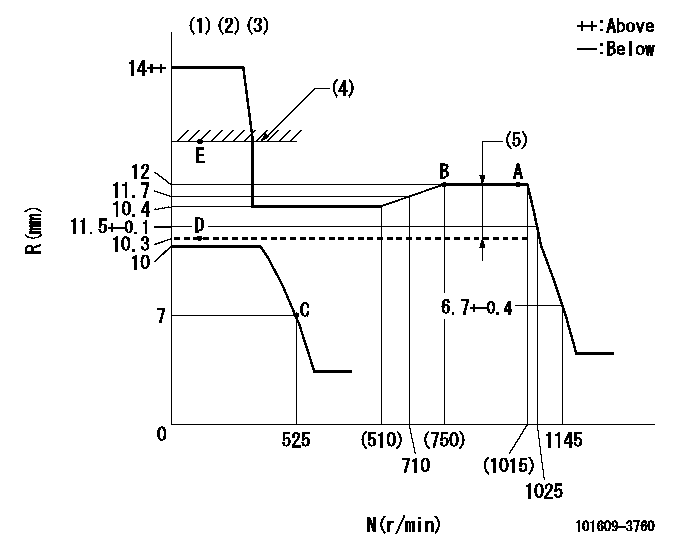
N:Pump speed
R:Rack position (mm)
(1)Target notch: K
(2)Tolerance for racks not indicated: +-0.05mm.
(3)It is not necessary to supply hydraulic pressure because the specification is for the hydraulic ACT normally ON.
(4)RACK LIMIT
(5)Boost compensator stroke: BCL
----------
K=13 BCL=(1.7)mm
----------
----------
K=13 BCL=(1.7)mm
----------
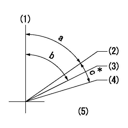
Speed control lever angle
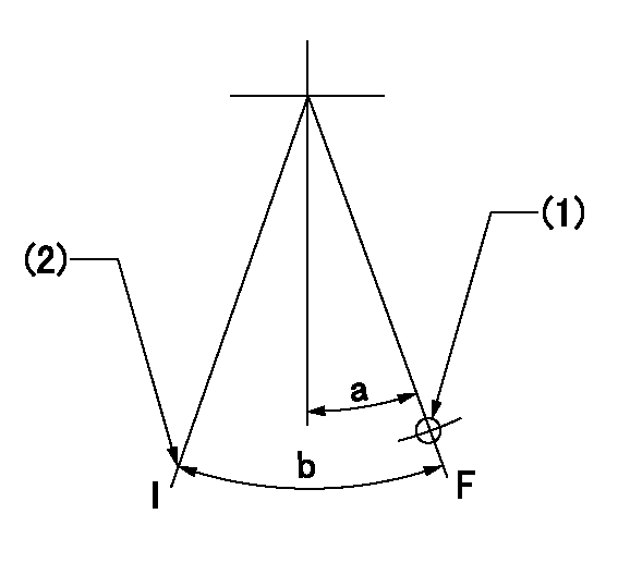
F:Full speed
I:Idle
(1)Use hole at R = aa (middle hole)
(2)Stopper bolt setting
----------
aa=77mm
----------
a=8deg+-5deg b=29deg+-5deg
----------
aa=77mm
----------
a=8deg+-5deg b=29deg+-5deg
Stop lever angle
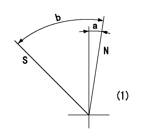
N:Pump normal
S:Stop the pump.
(1)No return spring
----------
----------
a=0deg+-5deg b=53deg+-5deg
----------
----------
a=0deg+-5deg b=53deg+-5deg
0000001501 I/P WITH LOAD PLUNGER ADJ
Adjusting procedure for load plunger equipped pump with RSV (cam lock) governor (see service information S.I. 434 for details).
At cam lift h+-0.01, set the camshaft c deg from the * mark in accordance with the timing adjustment procedure.
2. Align the flyweight's timing tooth position and the lock pin groove and then fully tighten the flyweight to the camshaft. Then, remove the lock pin.
3. Adjust the maximum variation between cylinders and injection quantity.
4. Adjust using the pre-stroke adjusting shim so that the pre-stroke value is the value for 4/4 load (standard point A).
5. After adjusting the pre-stroke, reconfirm that the injection quantity and the maximum variation between cylinders are as specified.
6. At delivery, again fix the flyweight using the lock pin.
----------
h=2.6+-0.01mm c=5deg30min+-30min
----------
----------
h=2.6+-0.01mm c=5deg30min+-30min
----------
0000001601 TAMPER PROOF
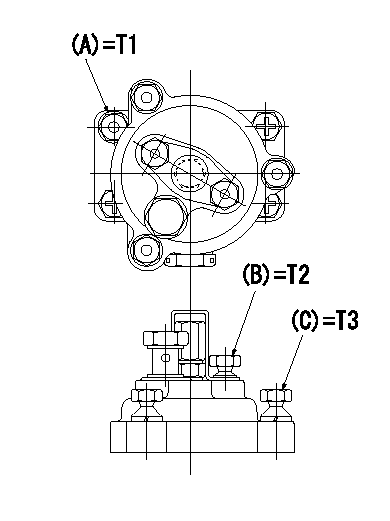
Tamperproofing-equipped boost compensator cover installation procedure
(1)After adjusting the governor and the boost compensator, tighten to the specified torque to break off the bolt heads.
(Tightening torque T = T1 maximum)
(2)After adjusting the governor and the boost compensator, tighten to the specified torque to break off the bolt heads.
(Tightening torque T = T2)
(3)After adjusting the governor and the boost compensator, tighten to the specified torque to break off the bolt heads.
(Tightening torque T = T3)
----------
T1=7.16~9.12N-m(0.73~0.93kgf-m) T2=2.9~4.4N-m(0.3~0.45kgf-m) T3=2.9~4.4N-m(0.3~0.45kgf-m)
----------
----------
T1=7.16~9.12N-m(0.73~0.93kgf-m) T2=2.9~4.4N-m(0.3~0.45kgf-m) T3=2.9~4.4N-m(0.3~0.45kgf-m)
----------
Timing setting
(1)Pump vertical direction
(2)Key groove position for No. 1 cylinder's cam lift h = cc (at BTDC aa).
(3)Key groove position for No. 1 cylinder's beginning of injection (at point A after injection quantity adjustment).
(4)Position of the key groove of the No. 1 cylinder at B.T.D.C. bb (fix the governor flyweight at this position for delivery).
(5)B.T.D.C.: aa
----------
aa=11deg bb=0deg cc=2.6+-0.01mm
----------
a=55deg18min+-3deg b=55deg18min+-3deg13min48sec c=5deg30min+-30min
----------
aa=11deg bb=0deg cc=2.6+-0.01mm
----------
a=55deg18min+-3deg b=55deg18min+-3deg13min48sec c=5deg30min+-30min
Information:
Start By:a. remove oil pumpb. remove oil pan plate 1. Turn the crankshaft until two pistons are at the bottom center. Remove connecting rod caps (1) from the two connecting rods. Remove the lower half of the rod bearing from the rod bearing cap.2. Push the connecting rods away from the crankshaft. Remove the upper half of the rod bearing from the connecting rod. Install the connecting rod bearings dry when the clearance checks are made. Put clean engine oil on the connecting rod bearings for final assembly.3. Install the upper half of the rod bearing in the connecting rod.4. Install the lower half of the rod bearing in the connecting rod cap. Be sure the tabs in the back of the connecting rod bearings are in the tab grooves of the connecting rod and cap. 5. Use Plastigage (A) to check the connecting rod bearing clearance.6. Put Plastigage (A) on the connecting rod bearing.7. Put 2P2506 Thread Lubricant on the threads of the rod bolts and seat surfaces of the nuts.
When connecting rod caps are installed, make sure the number on the side of the cap is next to and respective with the number on the side of the connecting rod.
Do not turn the crankshaft when Plastigage (A) is in position.
Do not use an impact wrench to tighten the nuts the additional 90°.
8. Install connecting rod cap (1). Install the nuts. Tighten the nuts to a torque of 40 4 N m (30 3 lb ft). Put a mark on each nut and the end of each bolt. Tighten the nuts 90° more. Remove the connecting rod caps. Remove Plastigage (A) and measure the width of the Plastigage. The connecting rod clearance must be 0.076 to 0.168 mm (.0030 to .0066 in) for new bearings. The maximum clearance with used bearings is 0.25 mm (.010 in).9. Install the connecting rod caps and tighten the nuts as in Step 8.10. Do Steps 1 through 9 for the remainder of the connecting rod bearings.End By:a. install oil pan plateb. install oil pump
Have questions with 101609-3760?
Group cross 101609-3760 ZEXEL
Komatsu
Komatsu
Komatsu
Komatsu
101609-3760
9 400 613 385
4063845
INJECTION-PUMP ASSEMBLY
6BTAA
6BTAA
101609-3760
9 400 613 385
6738711530
INJECTION-PUMP ASSEMBLY
6BTAA
6BTAA