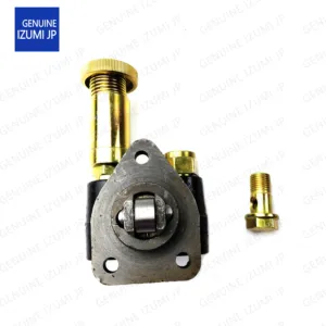
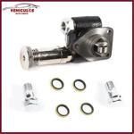
Information supply pump
BOSCH
F 01G 0V3 000
f01g0v3000
ZEXEL
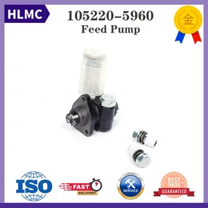
105220-5960
1052205960

Rating:
Compare Prices: .
As an associate, we earn commssions on qualifying purchases through the links below

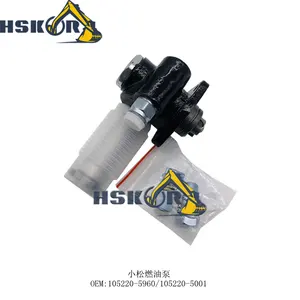
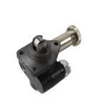
105220-5960 105220-5001 1052205960 1052205001 Fuel Feed Pump for S4S S4Q S4Q2 for Komatsu Engine 6D102 6D95 PC200-5 PC200-6 PC200-7 PC210-6 PC220-6 Transfer Lift Pump
Teaviatorial 🔥Part Name:Fuel Feed Pump || 🔥Part Number:105220-5960 105220-5001 1052205960 1052205001 || 🔥Application:S4S S4Q S4Q2 Engine 6D102 6D95 PC200-5 PC200-6 PC200-7 PC210-6 PC220-6 Transfer Lift Pumpv || 🔥Tip: If you need any other parts, please contact us - we are a professional sales team and have many products to offer to you. Many buyers are very satisfied with our service. You can get first-class products and high-quality services from us, believe me, you will have a pleasant shopping experience here. || 🔥Attention: If you are unsure if the product is suitable for your machine model. In order not to delay your use of the parts, please provide your engine nameplate or serial number and part number, and we will help you confirm if it is suitable. To avoid unnecessary returns, please carefully check the product image and part number to ensure that it is the product you want. Thank you for your support and understanding!
Teaviatorial 🔥Part Name:Fuel Feed Pump || 🔥Part Number:105220-5960 105220-5001 1052205960 1052205001 || 🔥Application:S4S S4Q S4Q2 Engine 6D102 6D95 PC200-5 PC200-6 PC200-7 PC210-6 PC220-6 Transfer Lift Pumpv || 🔥Tip: If you need any other parts, please contact us - we are a professional sales team and have many products to offer to you. Many buyers are very satisfied with our service. You can get first-class products and high-quality services from us, believe me, you will have a pleasant shopping experience here. || 🔥Attention: If you are unsure if the product is suitable for your machine model. In order not to delay your use of the parts, please provide your engine nameplate or serial number and part number, and we will help you confirm if it is suitable. To avoid unnecessary returns, please carefully check the product image and part number to ensure that it is the product you want. Thank you for your support and understanding!

for Excavator 105220-5960 105220-5001 for PC200 120 220-5-6-7 Fuel Manual Pump 6D102 6D95 Engine Excavator(6D102)
COKYIS Excavators || For Excavator 105220-5960 105220-5001 For PC200 120 220-5-6-7 Fuel Manual Pump 6D102 6D95 Engine Excavator
COKYIS Excavators || For Excavator 105220-5960 105220-5001 For PC200 120 220-5-6-7 Fuel Manual Pump 6D102 6D95 Engine Excavator
for Excavator 105220-5960 105220-5001 for PC200 120 220-5-6-7 Fuel Manual Pump 6D102 6D95 Engine Excavator(6D102)
DLKULJMR Excavators || For Excavator 105220-5960 105220-5001 For PC200 120 220-5-6-7 Fuel Manual Pump 6D102 6D95 Engine Excavator
DLKULJMR Excavators || For Excavator 105220-5960 105220-5001 For PC200 120 220-5-6-7 Fuel Manual Pump 6D102 6D95 Engine Excavator
You can express buy:
USD 56.22
19-06-2025
19-06-2025
S4S S6S S4Q2 6D95 6D102 Fuel Feed Pump 105220-5960 34461-09050 For Komatsu Mitsubishi Diesel Engine Repair Parts Kit
USD 15.8
14-06-2025
14-06-2025
Promotion Price PC200-5 PC200-6 Engine 6D95 6D102 105220-5960 105220-5001 Electric Fuel Transfer Pump for Excavator
USD 89.25
14-06-2025
14-06-2025
Disenparts Fuel Feed Pump 105220-5960 105220-5001 for Komatsu Engine 6D95 6D102 Excavator PC200-5 PC200-6 PC200-7 PC210-6
Images:
USD 14.5

[14-Jun-2025]
USD 691.19

[14-Jun-2025]
USD 89.25
[24-Jun-2025]
USD 86.74
[19-May-2025]
Scheme ###:
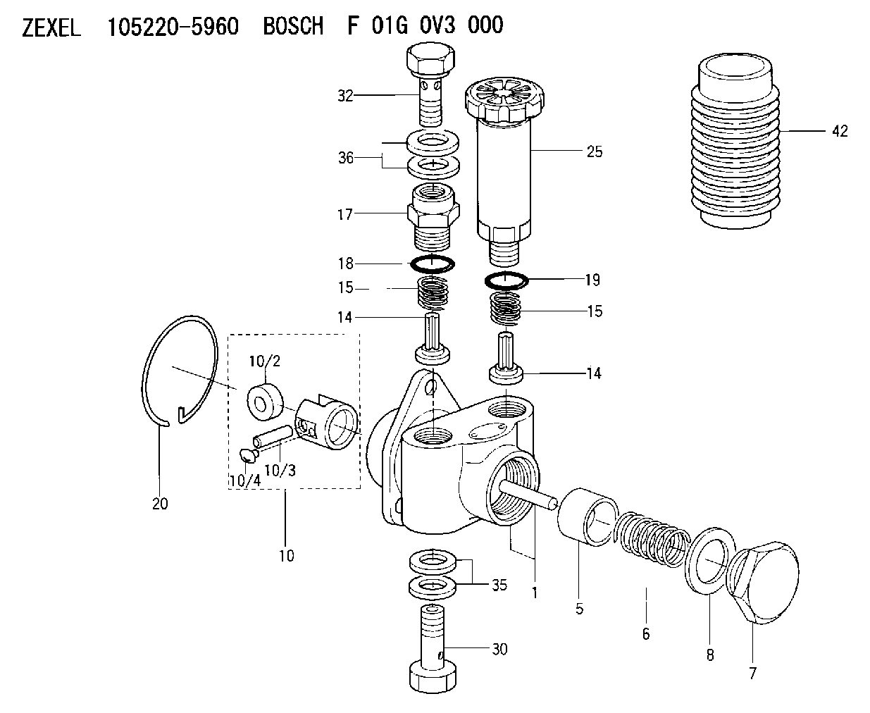
| 1. | [1] | 152003-1020 | PUMP HOUSING |
| 5. | [1] | 152100-1120 | PUMP PLUNGER |
| 6. | [1] | 152102-1600 | COMPRESSION SPRING |
| 7. | [1] | 152105-1600 | CAPSULE |
| 8. | [1] | 029332-6030 | GASKET |
| 10. | [1] | 152111-2820 | TAPPET |
| 10/2. | [1] | 152112-0100 | ROLLER |
| 10/3. | [1] | 152113-0700 | BEARING PIN |
| 10/4. | [2] | 152114-0400 | SLIDER |
| 14. | [2] | 152115-0500 | VALVE BODY |
| 14. | [2] | 152115-0500 | VALVE BODY |
| 15. | [2] | 152116-0200 | COILED SPRING |
| 15. | [2] | 152116-0200 | COILED SPRING |
| 17. | [1] | 152118-0900 | ADAPTOR |
| 18. | [1] | 029631-6060 | O-RING |
| 19. | [1] | 029631-6060 | O-RING |
| 20. | [1] | 152121-0200 | LOCKING WASHER |
| 25. | [1] | 152200-5420 | HAND PRIMER |
| 30. | [1] | 152300-5920 | EYE BOLT |
| 32. | [1] | 029731-4680 | EYE BOLT |
| 35. | [2] | 029341-4130 | GASKET D20&13.8T2* |
| 36. | [2] | 029341-4130 | GASKET D20&13.8T2* |
| 42. | [1] | 152320-0100 | COVER |
Include in #1:
101402-3771
as SUPPLY PUMP
Cross reference number
Zexel num
Bosch num
Firm num
Name
Information:
This instruction is written for electronic technicians only, and must not be used by service personnel with no training or knowledge of electronics. For repairs that can be done by the Caterpillar Dealer Serviceman, with no knowledge of electronics, see Special Instruction Form SMHS6964 "Using 1P3500 and 2P8280 Injection Timing Groups."As an aid to the technician for troubleshooting the inverter and timing light, the following information is given in this instruction:1. Circuit board illustrations showing the position of each of the components and the test points (T) for using a voltmeter or an oscilloscope.2. Schematics of the electrical circuit so the technician can easily follow the sequence of the circuit.3. Test point values.4. Electrical parts replacement information.5. Timing light calibration procedure.Timing Light
1P3500 And 2P8280 Timing Lights - Electrical Schematic, Test Points And Parts List
Inverter - Electrical Schematic, Test Points And Parts List
There is a two position switch that is marked ADV.-RPM on the side of the 1P3499 Timing Light. When the timing light is in use, operation of the ADV.-RPM switch is as follows:RPM Position
A fuel injection pulse opens the switch in the transducer and starts a positive pulse (TP9) of fixed duration, from the monostable composed of Q2 and Q3. This pulse turns on a transistor switch Q4, allowing current to pass through meter M1, which mechanically averages pulses from an operating engine, and is calibrated to read RPM. Switch S2 grounds the gate of SCR1 to prevent the flash tube from strobing.ADV. Position
A fuel injection pulse again starts a pulse from the monostable. Adjustment of R7, the TIME-ADVANCE control, now determines the pulse duration from the monostable. When R7 is adjusted so that TDC on the damper coincides with the pointer on the block of an operating engine, the monostable pulse duration is exactly the same as the fuel system advance measured in seconds. Transistor switch Q4 again turns on, allowing current to pass through meter M1, causing a meter indicator that is calibrated in degrees of advance instead of seconds.Electrical Calibration Procedure
Before the electrical calibration can be done, the following equipment must be obtained.1) Oscilloscope with triggered sweep. Heath Co. M/N SO-4530 or equivalent.2) Signal generator. Heath M/N SG-72A or equivalent.3) Electronic counter. Data Precision M/N 5740 or equivalent.4) Electronic switch (dealer built).Calibration Procedure
(1) Hold the 1P3499 Timing Light in the same position (about a 45° angle) as if measuring the timing advance on an engine, and check the mechanical meter zero. Make an adjustment to zero if necessary. (2) To remove the protective rubber boot from the flash tube, twist the rubber boot and pull it away from the timing light as shown. (3) Remove the right side (side that has the serial number tag) of the timing light case.(4) Connect the 1P3499 Timing Light to a circuit like the one that follows. This will simulate (be the same as) a fuel flow transducer on an engine that is operating at 2400 RPM. (5) Turn the TIME-ADV. control counterclockwise (CCW) to its minimum