Information actuator
BOSCH
9 420 612 065
9420612065
ZEXEL
105952-1130
1059521130
Rating:
Scheme ###:
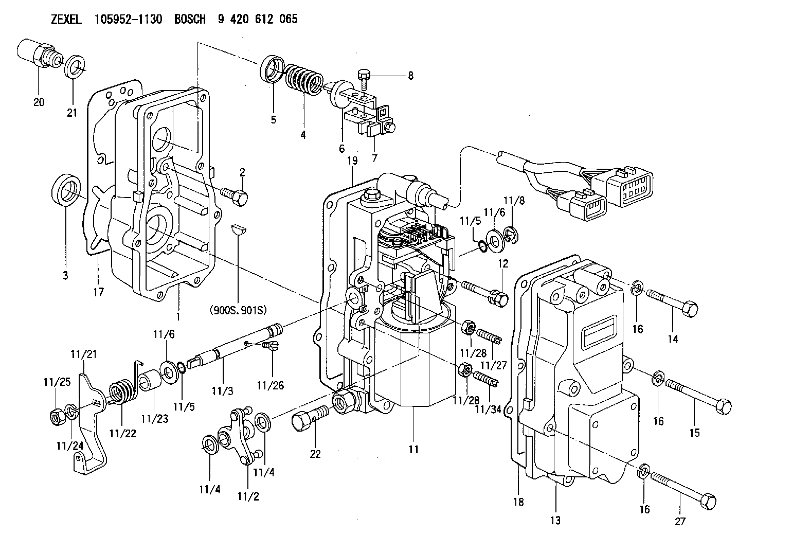
| 1. | [1] | 159560-0100 | GOVERNOR HOUSING |
| 2. | [8] | 139006-4100 | BLEEDER SCREW |
| 3. | [1] | 029621-7050 | PACKING RING |
| 4. | [1] | 159564-0000 | COILED SPRING |
| 5. | [1] | 159564-4000 | SLOTTED WASHER |
| 6. | [1] | 159564-4100 | SLOTTED WASHER |
| 7. | [1] | 159564-7321 | CONNECTOR |
| 7. | [1] | 159636-3121 | CONNECTOR |
| 7B. | [1] | 159636-3321 | CONNECTOR |
| 7C. | [1] | 159636-3521 | CONNECTOR |
| 8. | [1] | 020105-1240 | BLEEDER SCREW M5P0.8L12 |
| 9. | [1] | 159564-0501 | PLATE |
| 9B. | [1] | 159564-6500 | PLATE |
| 9C. | [1] | 159584-5200 | PLATE |
| 10. | [1] | 020105-1240 | BLEEDER SCREW M5P0.8L12 |
| 11. | [1] | 159569-2920 | ACTUATOR |
| 11/1. | [1] | 159562-0720 | PLATE;GOV. |
| 11/2. | [1] | 159583-1020 | STRAP |
| 11/3. | [1] | 159563-1700 | LEVER SHAFT |
| 11/4. | [2] | 029311-0170 | SHIM |
| 11/4. | [2] | 029311-0170 | SHIM |
| 11/5. | [2] | 016500-0710 | O-RING |
| 11/5. | [2] | 016500-0710 | O-RING |
| 11/6. | [2] | 014011-0140 | PLAIN WASHER D22&10.5T1.6 |
| 11/6. | [2] | 014011-0140 | PLAIN WASHER D22&10.5T1.6 |
| 11/8. | [1] | 016010-0940 | LOCKING WASHER |
| 11/9. | [1] | 159585-0720 | LINEAR DC MOTOR |
| 11/10. | [4] | 139006-9100 | BLEEDER SCREW |
| 11/11. | [1] | 159566-2420 | RACK SENSOR |
| 11/12. | [4] | 020105-2040 | BLEEDER SCREW M5P0.8L20 |
| 11/16. | [1] | 159565-2400 | LIP |
| 11/17. | [1] | 159568-6821 | CABLE SET |
| 11/18. | [2] | 020106-1440 | BLEEDER SCREW M6P1.0L14 |
| 11/19. | [1] | 134002-0200 | ADAPTOR |
| 11/21. | [1] | 159563-7120 | CONTROL LEVER |
| 11/22. | [1] | 159563-4800 | COILED SPRING |
| 11/23. | [1] | 159563-1800 | BUSHING |
| 11/24. | [1] | 014110-8440 | LOCKING WASHER |
| 11/25. | [1] | 013030-8140 | UNION NUT M8P1.25H5 |
| 11/26. | [1] | 159563-1000 | FLAT-HEAD SCREW |
| 11/27. | [1] | 155615-1700 | FLAT-HEAD SCREW |
| 11/28. | [2] | 029240-6010 | UNION NUT M6P1.0H5* |
| 11/28. | [2] | 029240-6010 | UNION NUT M6P1.0H5* |
| 11/34. | [1] | 159563-8400 | FLAT-HEAD SCREW |
| 12. | [2] | 020106-4040 | BLEEDER SCREW |
| 13. | [1] | 159561-0400 | GOVERNOR COVER |
| 14. | [4] | 010006-7040 | BLEEDER SCREW M6P1L70 |
| 15. | [2] | 010006-5540 | BLEEDER SCREW M6P1L55 4T |
| 16. | [8] | 014110-6440 | LOCKING WASHER |
| 16. | [8] | 014110-6440 | LOCKING WASHER |
| 16. | [8] | 014110-6440 | LOCKING WASHER |
| 17. | [1] | 154371-5600 | GASKET |
| 18. | [1] | 154390-0400 | GASKET |
| 19. | [1] | 154390-0500 | GASKET |
| 20. | [1] | 155404-3400 | CAP |
| 21. | [1] | 026524-3040 | GASKET |
| 22. | [1] | 029731-4680 | EYE BOLT |
| 27. | [2] | 139006-1300 | BLEEDER SCREW M6P1L76 |
| 900S. | [1] | 025803-1310 | WOODRUFF KEY |
| 901S. | [1] | 025803-1610 | WOODRUFF KEY |
Cross reference number
Zexel num
Bosch num
Firm num
Name
105952-1130
9 420 612 065
ACTUATOR
K
K
Information:
Filters and Pump Housing
1. Open the bleed valve on the pump housing. 2. Unscrew the hand priming pump plunger until it can be pulled out by hand. 3. Move the plunger in and out until fuel flows, free of air bubbles, from the bleed valve. 4. Close the bleed valve. 5. Push the plunger in and tighten by hand.6. Start the engine and check for leaks.Injection Pumps and Lines
The injection pumps and high pressure lines must be primed if the engine will not start, or runs rough, after priming the filters and pump housing.Each injection pump has a reverse flow check valve. These cannot be opened with hand priming pump pressure. Use the following procedure to prime the injection pumps and lines.
The fuel injection nozzles can be permanently damaged by twisting if only one wrench is used to loosen or tighten the fuel line nuts. Use one wrench to hold the nozzle and another to loosen the nut.
1. Loosen each of the fuel line nuts at the cylinder head end.2. Crank the engine with the starting motor until fuel flows, free of air bubbles, from each of the injection lines. Stop cranking the engine.3. Tighten each of the fuel line nuts to a torque of 41 + 7 N m (30 + 5 lb. ft.). Use a second wrench on the nozzle to prevent damage to it.4. Start the engine and check for leaks.
Have questions with 105952-1130?
Group cross 105952-1130 ZEXEL
Mitsubishi
105952-1130
9 420 612 065
ACTUATOR