Information actuator
BOSCH
9 420 613 655
9420613655
ZEXEL
105952-1110
1059521110
MITSUBISHI
ME738517
me738517
Rating:
Scheme ###:
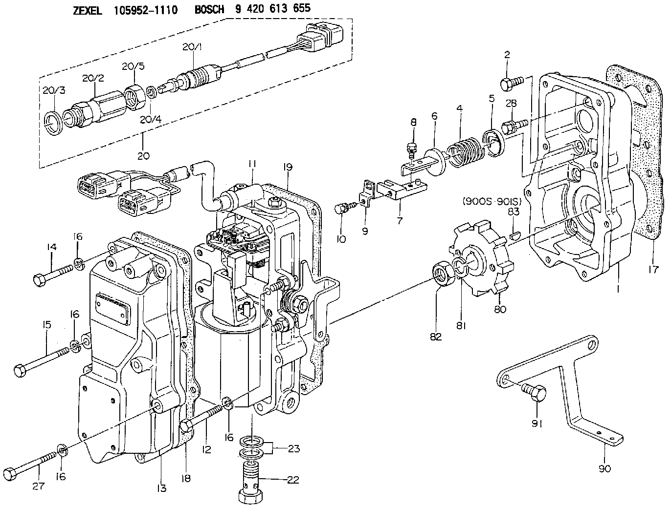
| 1. | [1] | 159560-0900 | GOVERNOR HOUSING |
| 2. | [8] | 139006-4100 | BLEEDER SCREW |
| 4. | [1] | 159564-0000 | COILED SPRING |
| 5. | [1] | 159564-4000 | SLOTTED WASHER |
| 6. | [1] | 159564-4100 | SLOTTED WASHER |
| 7. | [1] | 159564-7320 | CONNECTOR |
| 8. | [1] | 020105-1240 | BLEEDER SCREW M5P0.8L12 |
| 9. | [1] | 159564-0501 | PLATE |
| 10. | [1] | 020105-1240 | BLEEDER SCREW M5P0.8L12 |
| 11. | [1] | 159569-2720 | ACTUATOR |
| 12. | [2] | 020106-4040 | BLEEDER SCREW |
| 13. | [1] | 159561-0700 | GOVERNOR COVER |
| 14. | [4] | 010006-7040 | BLEEDER SCREW M6P1L70 |
| 15. | [2] | 010006-5540 | BLEEDER SCREW M6P1L55 4T |
| 16. | [8] | 014110-6440 | LOCKING WASHER |
| 16. | [8] | 014110-6440 | LOCKING WASHER |
| 16. | [8] | 014110-6440 | LOCKING WASHER |
| 16. | [8] | 014110-6440 | LOCKING WASHER |
| 17. | [1] | 159566-0400 | GASKET |
| 18. | [1] | 154390-0400 | GASKET |
| 19. | [1] | 154390-0500 | GASKET |
| 20. | [1] | 154611-0420 | RACK SENSOR ASSY |
| 20/1. | [1] | 479742-8620 | RACK SENSOR |
| 20/2. | [1] | 154614-4800 | JOINT CONNECTION |
| 20/3. | [1] | 026524-3040 | GASKET |
| 20/4. | [1] | 029310-6260 | SHIM D11.5&6.4T1.00 |
| 20/5. | [1] | 154614-1900 | UNION NUT |
| 22. | [1] | 153556-4800 | EYE BOLT |
| 23. | [2] | 029331-2120 | GASKET |
| 27. | [2] | 139006-1300 | BLEEDER SCREW M6P1L76 |
| 28. | [1] | 139006-5800 | BLEEDER SCREW |
| 80. | [1] | 159564-9200 | TOOTHED GEAR |
| 81. | [1] | 014111-2420 | LOCKING WASHER |
| 82. | [1] | 013031-2120 | UNION NUT |
| 83. | [1] | 025803-1610 | WOODRUFF KEY |
| 90. | [1] | 159564-9100 | BRACKET |
| 91. | [1] | 020000-2040 | BLEEDER SCREW M10P1.5L20 |
| 900S. | [1] | 025803-1310 | WOODRUFF KEY |
| 901S. | [1] | 025803-1610 | WOODRUFF KEY |
Include in #1:
108622-2020
as GOVERNOR
Cross reference number
Zexel num
Bosch num
Firm num
Name
Information:
Starting From External Electrical Source
Always wear protective glasses when working with batteries.Do not allow the free end of booster cables to make contact with each other or touch the engine. This will help prevent sparks near the batteries.Batteries give off flammable fumes that can explode.Do not smoke when observing the battery electrolyte levels.Electrolyte is an acid and can cause personal injury if it contacts skin or eyes.
Be sure the main power switch is in the OFF position before attaching the booster cables to the engine being started. When using booster cables, be sure to connect in parallel: POSITIVE (+) to POSITIVE (+) and NEGATIVE (-) to NEGATIVE (-).Use only equal voltage for boost starting. The use of a welder or higher voltage will damage the electrical system.
Engines without engine-to-frame ground straps can be damaged by electrical discharge.To prevent electrical discharge damage, check to make sure there is an engine-to-frame ground strap. For engines which have the alternator connected to an engine component, the ground strap must connect that component to the frame.Some engines have starter-to-frame ground straps. But, many of these starters are not electrically grounded to the engine. They have electrical insulation systems. For this reason, the starter-to-frame ground strap may not be an acceptable ground.Connect one end of cable to the POSITIVE (+) (ungrounded) terminal of the battery on the engine being started. Connect the other end to the POSITIVE (+) terminal of the power source.Connect one end of the second cable to the NEGATIVE (-) terminal of the power source. Connect the other end to the frame of the engine to be started.Turn the start switch on and start the engine.Disconnect the cable from the frame first. Disconnect the other end from the NEGATIVE (-) terminal of the power source. Disconnect the cable from the POSITIVE (+) terminal of the battery. Disconnect the other end from the POSITIVE (+) terminal of the power source.