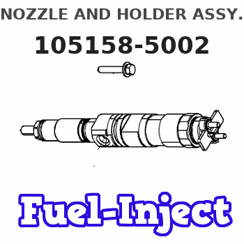
Information nozzle and holder assy.
BOSCH
F 01G 0V4 000
f01g0v4000
ZEXEL
105158-5002
1051585002
KOMATSU
4063212
4063212
Rating:
Compare Prices: .
As an associate, we earn commssions on qualifying purchases through the links below

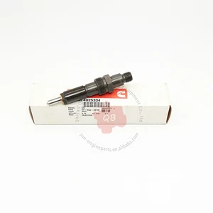
6BT 6BT5.9 6BTA5.9 6BTA 5.9 355/370 CPL 2208, 8457 common rail fuel injector 3802833 4025334 4063212 4063321
Generic
Generic

Compatible with Cummins Engine Fuel Injector Parts 4BT 6B 6BT Model 4063212 & 4025334 Made of Steel (4BT 6B 6BT)
Generic Compatible with Cummins Engine Fuel Injector Parts 4BT 6B 6BT Model 4063212 & 4025334 Made of Steel
Generic Compatible with Cummins Engine Fuel Injector Parts 4BT 6B 6BT Model 4063212 & 4025334 Made of Steel

F01G0V4000 Supply 6BT Diesel Engine Parts High Pressure Fuel Common Rail Injector Assembly
FICMVLQC By adopting high-precision processing techniques, the dimensions of each component of the fuel injector are ensured to be precise, guaranteeing the accuracy and stability of fuel injection. || It can fully atomize diesel fuel, enabling better mixture of fuel and air, and promoting efficient combustion. || It is usually manufactured with high-strength, high-temperature-resistant and corrosion-resistant alloy materials to ensure long-term stable operation. || It has excellent sealing performance, preventing fuel leakage and ensuring stable fuel injection pressure. || F01G0V4000 Supply 6BT Diesel Engine Parts High Pressure Fuel Common Rail Injector Assembly
FICMVLQC By adopting high-precision processing techniques, the dimensions of each component of the fuel injector are ensured to be precise, guaranteeing the accuracy and stability of fuel injection. || It can fully atomize diesel fuel, enabling better mixture of fuel and air, and promoting efficient combustion. || It is usually manufactured with high-strength, high-temperature-resistant and corrosion-resistant alloy materials to ensure long-term stable operation. || It has excellent sealing performance, preventing fuel leakage and ensuring stable fuel injection pressure. || F01G0V4000 Supply 6BT Diesel Engine Parts High Pressure Fuel Common Rail Injector Assembly
You can express buy:
USD 106.85
14-06-2025
14-06-2025
4025334 Engine Parts Thailand Cummins 6BT Fuel Injector 4063212 4025334
Include in #1:
101405-3290
as NOZZLE AND HOLDER ASSY
Cross reference number
Zexel num
Bosch num
Firm num
Name
105158-5002
4063212 KOMATSU
NOZZLE AND HOLDER ASSY.
6BTAA K 53LP NOZZLE & HOLDER ASSY N&NH
6BTAA K 53LP NOZZLE & HOLDER ASSY N&NH
Information:
Introduction
This Special Instruction covers the removal procedure for DEF connectors on the models and applications listed above.Safety Section
Care must be taken to ensure that fluids are contained during performance of inspection, maintenance, testing, adjusting, and repair of the product. Be prepared to collect the fluid with suitable containers before opening any compartment or disassembling any component containing fluids.Refer to Special Publication, PERJ1017, "Dealer Service Tool Catalog" for tools and supplies suitable to collect and contain fluids on Cat® products.Dispose of all fluids according to local regulations and mandates.
Personal injury or death can result from improperly checking for a leak.Always use a board or cardboard when checking for a leak. Escaping air or fluid under pressure, even a pin-hole size leak, can penetrate body tissue causing serious injury, and possible death.If fluid is injected into your skin, it must be treated immediately by a doctor familiar with this type of injury.
Illustration 1 g00104545Prevent the machine from movement. Park the machine on a level surface.Attach a "Do Not Operate" warning tag or a similar warning tag to the start switch or to the controls before you service the equipment. These warning tags (Special Instruction, SEHS7332) are available from your Caterpillar dealer.Removal Procedure for Single Clip Connectors
Illustration 2 g03468077
(1) Line
(2) Retaining Clip
Clean the area around the connector with compressed air. Be sure to remove any dirt or debris before continuing with this procedure.
Press down on the line (1).
Press IN on the retaining clip (2).
Gently pull straight up on the line.Note: Do not pull out the clip, damage will occur to the retaining clip.Note: Do not pull off the line without the clip being fully depressed, damage will occur to the retaining clip.Removal Procedure for Dual Clip Connectors
Illustration 3 g03468506
(1) Line
(2) Retaining Clips
Clean the area around the connector with compressed air. Be sure to remove any dirt or debris before continuing with this procedure.
Press down on the line (1).
Press IN on the retaining clips (2).
Gently pull straight up on the line.Note: Do not pull out the clip, damage will occur to the retaining clip.Note: Do not pull off the line without the clip being fully depressed, damage will occur to the retaining clip.