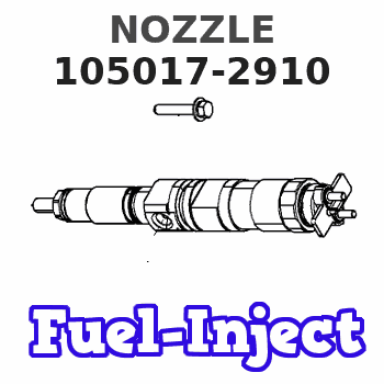
Information nozzle
BOSCH
F 01G 0V5 000
f01g0v5000
ZEXEL
105017-2910
1050172910
KOMATSU
4063321
4063321
Rating:
Compare Prices: .
As an associate, we earn commssions on qualifying purchases through the links below

6BT 6BT5.9 6BTA5.9 6BTA 5.9 355/370 CPL 2208, 8457 common rail fuel injector 3802833 4025334 4063212 4063321
Generic
Generic

Congparts Fuel Injector 4025334 4063212 4063321 105158-5002 H105158500 Compatible with Cummins Engine 6BT5.9 ISB5.9 QSB5.9 4BT 6B 6BT Compatible with Zexel
Congparts Part Number: 4025334 4063212 4063321 105158-5002 H105158500 || Compatible with Cummins Engine 6BT5.9 ISB5.9 QSB5.9 4BT 6B 6BT Compatible with Zexel || Package Included: 1 x Fuel Injector || Easy Installation.Stable Characteristics High Reliability || It Is a Replacement Part Not Original Part. But It Can Work Good For You
Congparts Part Number: 4025334 4063212 4063321 105158-5002 H105158500 || Compatible with Cummins Engine 6BT5.9 ISB5.9 QSB5.9 4BT 6B 6BT Compatible with Zexel || Package Included: 1 x Fuel Injector || Easy Installation.Stable Characteristics High Reliability || It Is a Replacement Part Not Original Part. But It Can Work Good For You

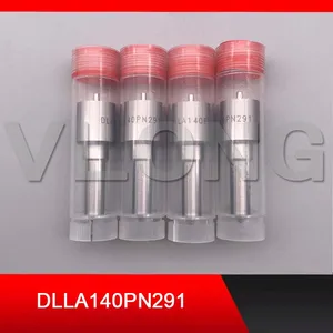
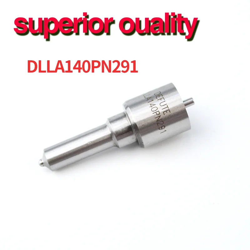
8PCS OEM # DLLA140PN291 105017-2910 1050172910 Excavator Fuel Injector Nozzles Compatible For Komatsu S6D102 PC200-7 6BTAA Engine
BTXHVKKP Direct installation, easy to use. || Stable characteristics make your car more fuel-efficient. || Use the latest fuel injection calibration for flow matching. || High-efficiency atomization can fully burn fuel and release the powerful power of the engine. || 8PCS OEM # DLLA140PN291 105017-2910 1050172910 Excavator Fuel Injector Nozzles Compatible For Komatsu S6D102 PC200-7 6BTAA Engine
BTXHVKKP Direct installation, easy to use. || Stable characteristics make your car more fuel-efficient. || Use the latest fuel injection calibration for flow matching. || High-efficiency atomization can fully burn fuel and release the powerful power of the engine. || 8PCS OEM # DLLA140PN291 105017-2910 1050172910 Excavator Fuel Injector Nozzles Compatible For Komatsu S6D102 PC200-7 6BTAA Engine
You can express buy:
USD 26
19-05-2025
19-05-2025
PN Type Nozzle Fuel Jet Spray Diesel Injector Sprayer Nozzle DLLA 140 PN 291 105017-2910 F01G0V5000 NP-DLLA140PN291 DLLA140PN291
USD 15.5
13-05-2025
13-05-2025
4 Pieces DLLA140PN291 Engine Accessories Premium fuel common rail nozzle 105017-2910 is suitable for Komatsu PCP200-7 SD102
Images:
USD 4

[13-May-2025]
USD 84.99

[10-Nov-2022]
USD 25

[24-Jun-2019]
Include in #1:
101405-3250
as NOZZLE
Cross reference number
Zexel num
Bosch num
Firm num
Name
Information:
Table 1
Required Parts
Item Qty New Part Number Part Name Former Part Number(1)
1 1 573-8722 Coolant Tank As 469-9108
2 1 586-9617 Bracket As 491-3429
3 1 570-0813 Hose 474-9783
(1) The former part number listed is for reference only and may differ.Refer to "Replacement Procedure" for the procedure to install a new coolant tank assembly (1).Replacement Procedure
Illustration 1 g06464028
(A) Hood
Illustration 2 g06464029
(B) Tank assembly
Remove hood (A) to gain access to tank assembly (B).
Illustration 3 g06464030
(B) Tank assembly
(C) Hose
(D) Clamp
Disconnect hose (C) from tank assembly (B) by removing clamp (D).
Illustration 4 g06464533
(E) Special connector
(F) Hose assembly
(H) Clips
Illustration 5 g06464539
(G) Bolts
Disconnect special connector (E). Remove tank assembly with hose assembly (F) by removing bolts (G). Remove clips (H) and special connector (E) from hose assembly (F).
Illustration 6 g06464548
(K) Bracket
(L) Bolts
Remove bracket (K) by removing bolts (L).
Illustration 7 g06464563
(1) 573-8722 Coolant Tank As
(3) 570-0813 Hose
(E) Special connector
(H) Clips
Illustration 8 g06464617
(D1) 27 degrees
(D2) 15 mm (0.6 inch)
(D3) 10 mm (0.4 inch)
Sub-assemble new tank assembly (1), hose (3), and special connector (E) with clips (H).Note: Align hose (3) and special connector (E) at the correct angle. Refer to Illustration 7 and 8 for proper alignment.
Illustration 9 g06464631
(2) 586-9617 Bracket As
(L) Bolts
Install new bracket assembly (2) with bolts (L). Torque bolts (L) to 12 3 N m (106.2 26.6 lb in)
Illustration 10 g06464633
(1) 573-8722 Coolant Tank As
(E) Special connector
(G) Bolts
Install tank assembly (1) with bolts (G) and connect special connector (E). Tighten bolts (G) to 12 3 N m (106.2 26.6 lb in).
Illustration 11 g06464637
(1) 573-8722 Coolant Tank As
(C) Hose
(D) Clamp
Reconnect hose (C) to the tank assembly (1) with clamp (D).
Reinstall hood. Refer to Step 1.