Information nozzle
BOSCH
9 432 610 295
9432610295
ZEXEL
105007-1300
1050071300
MITSUBISHI
ME731688
me731688

Rating:
Compare Prices: .
As an associate, we earn commssions on qualifying purchases through the links below

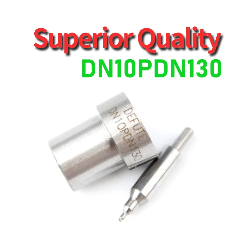
4Pcs DN10PDN130 Engine Injector Nozzles Compatible With Mitsubishi Pajero Triton 4D56 Diesel 2.5 1993-2002 0120001
EPIVORMEX Adapted to a variety of fuels, the vehicle is more flexible to use. || Adapted to a variety of engine management systems, the design and selection are more flexible. || Accurately control fuel injection quantity and time, improve power and reduce fuel consumption. || Fast response to commands, sufficient power under dynamic conditions, and more sensitive driving control. || Fuel atomization is fine, which enlarges the contact area with air, promotes combustion and reduces emissions.
EPIVORMEX Adapted to a variety of fuels, the vehicle is more flexible to use. || Adapted to a variety of engine management systems, the design and selection are more flexible. || Accurately control fuel injection quantity and time, improve power and reduce fuel consumption. || Fast response to commands, sufficient power under dynamic conditions, and more sensitive driving control. || Fuel atomization is fine, which enlarges the contact area with air, promotes combustion and reduces emissions.

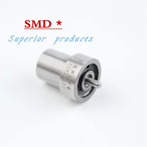
Diesel Injector Spray Nozzle 105007-1300 DN10PDN130 Compatible For MITSUBISHI 4D56
KSBGTOMW Optimal fuel atomization and combustion efficiency || Compatible For MITSUBISHI 4D56 engines, ensuring a perfect fit and reliable performance || Durable construction designed to withstand high pressure and temperature conditions || Easy installation process, saving you time and effort on engine repairs || Enhances engine performance and fuel economy, reducing emissions for a cleaner environment
KSBGTOMW Optimal fuel atomization and combustion efficiency || Compatible For MITSUBISHI 4D56 engines, ensuring a perfect fit and reliable performance || Durable construction designed to withstand high pressure and temperature conditions || Easy installation process, saving you time and effort on engine repairs || Enhances engine performance and fuel economy, reducing emissions for a cleaner environment

You can express buy:
USD 4.66
13-05-2025
13-05-2025
DN10PDN130 Diesel injector with 105007-1300 injector for Ruifeng 4D56T 2.5TD and modern injector D0331
USD 3.5
13-05-2025
13-05-2025
Diesel Injector Spray Nozzle 105007-1300 DN10PDN130 for MITSUBISHI 4D56
USD 10.46
16-05-2025
16-05-2025
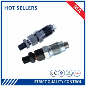
105007-1300 Injector DN10PDN130 Nozzle Diesel Engine Fuel Engine Injector Assembly Automotive Parts THYJA17S38
Images:
USD 3.5

[12-Nov-2023]
USD 5.18

[19-Dec-2024]
USD 60

[10-Nov-2022]
USD 5.99

[13-May-2025]
Include in #2:
104700-3001
as NOZZLE
Cross reference number
Zexel num
Bosch num
Firm num
Name
Information:
2. Remove the four bolts (2) that hold flange to aftercooler cover. Loosen clamp (6) on the turbocharger, and turn housing until inlet pipe is away from camshaft housing.3. Remove the oil drain line for the turbocharger.4. Disconnect the wiring from the glow plugs.5. Remove the inner fuel injection lines (4).6. Disconnect the outer fuel injection lines from the camshaft housing.7. Disconnect the wiring (3) for the glow plugs from the camshaft housing.8. Remove lifting bracket (1) from housing. 9. Remove the two bolts (7), nuts (8), and locks.10. Remove the bolts (5) that hold the camshaft housing in position. 11. Fasten a hoist to the camshaft housing. Remove camshaft housing (9). Weight of housing is 100 lb. (45 kg).Install Camshaft Housing
1. Turn all adjustment screws counterclockwise as far as possible to get maximum valve lash. Turn the camshafts until the "V" timing marks on drive gears (2) and (3) are in alignment as shown. Install the timing pin in timing hole in camshaft housing.2. Check to be sure the No. 1 piston is at the "TOP CENTER COMPRESSION" position, and the timing bolt is installed in flywheel.
The procedure in Steps 1 and 2 must be followed or damage to the engine may result.
3. Fasten a hoist and put camshaft housing in position on engine with gear (3) engaged with gear (4) in cylinder head. Install the bolts (1), nuts, and locks that hold the camshaft housing in position. Install lifting bracket (5).4. Connect the fuel injection lines to outside of camshaft housing. Install inner lines. Tighten the nuts on lines to 30 5 lb.ft. (4.1 0.7 mkg).5. Remove the timing pin from camshaft housing and timing bolt from flywheel.6. Make the valve lash adjustment as follows: Make an adjustment to exhaust valves for cylinders 1-3-5 and inlet valves for cylinders 1-2-4. Turn the crankshaft 360° so No. 6 piston is at "TOP CENTER COMPRESSION" position. Make an adjustment to exhaust valves for cylinders 2-4-6 and inlet valves for cylinders 3-5-6.a) Turn screws clockwise until there is zero clearance between the button on screw and the valve.b) Turn screws counterclockwise four clicks to get .008 in. (0.2 mm) clearance for the inlet valves.c) Turn screws counterclockwise ten clicks to get .020 in. (0.5 mm) clearance for the exhaust valves.7. Connect the wiring for the glow plugs. Install the oil drain line for the turbocharger.8. Turn the housing to put pipe (6) into position, and install the four bolts. Tighten clamp (7).end by: a) install valve coverb) install alternatorDisassemble Camshaft Housing
start by: a) remove camshaft housing 1. Remove the four bolts (3) and lock from each drive gear. Remove the camshaft drive gears (1) and (2). 2. Remove the two bolts (5), lock, and plate (4) that hold camshafts in position. 3. Remove the inlet camshaft (6) and exhaust camshaft (7) from housing.4. Remove lifting bracket (8) from end of camshaft housing. 5. Remove the two bolts (11) that hold the rocker shafts in position.6. Remove the