Information injection-pump assembly
BOSCH
9 400 618 263
9400618263
ZEXEL
106871-8272
1068718272
HINO
220203193A
220203193a
Rating:
Service parts 106871-8272 INJECTION-PUMP ASSEMBLY:
1.
_
7.
COUPLING PLATE
8.
_
9.
_
11.
Nozzle and Holder
236002071A
12.
Open Pre:MPa(Kqf/cm2)
21.6(220)
15.
NOZZLE SET
Include in #1:
106871-8272
as INJECTION-PUMP ASSEMBLY
Cross reference number
BOSCH
9 400 618 263
9400618263
ZEXEL
106871-8272
1068718272
HINO
220203193A
220203193a
Zexel num
Bosch num
Firm num
Name
106871-8272
9 400 618 263
220203193A HINO
INJECTION-PUMP ASSEMBLY
EF750-TI * K 14CD INJECTION PUMP ASSY PE8P PE
EF750-TI * K 14CD INJECTION PUMP ASSY PE8P PE
Calibration Data:
Adjustment conditions
Test oil
1404 Test oil ISO4113 or {SAEJ967d}
1404 Test oil ISO4113 or {SAEJ967d}
Test oil temperature
degC
40
40
45
Nozzle and nozzle holder
105780-8140
Bosch type code
EF8511/9A
Nozzle
105780-0000
Bosch type code
DN12SD12T
Nozzle holder
105780-2080
Bosch type code
EF8511/9
Opening pressure
MPa
17.2
Opening pressure
kgf/cm2
175
Injection pipe
Outer diameter - inner diameter - length (mm) mm 8-3-600
Outer diameter - inner diameter - length (mm) mm 8-3-600
Overflow valve
134424-3120
Overflow valve opening pressure
kPa
127
107
147
Overflow valve opening pressure
kgf/cm2
1.3
1.1
1.5
Tester oil delivery pressure
kPa
157
157
157
Tester oil delivery pressure
kgf/cm2
1.6
1.6
1.6
Direction of rotation (viewed from drive side)
Right R
Right R
Injection timing adjustment
Direction of rotation (viewed from drive side)
Right R
Right R
Injection order
1-8-6-2-
7-5-4-3
Pre-stroke
mm
4.5
4.44
4.5
Beginning of injection position
Drive side NO.1
Drive side NO.1
Difference between angles 1
Cal 1-8 deg. 45 44.75 45.25
Cal 1-8 deg. 45 44.75 45.25
Difference between angles 2
Cal 1-6 deg. 90 89.75 90.25
Cal 1-6 deg. 90 89.75 90.25
Difference between angles 3
Cyl.1-2 deg. 135 134.75 135.25
Cyl.1-2 deg. 135 134.75 135.25
Difference between angles 4
Cal 1-7 deg. 180 179.75 180.25
Cal 1-7 deg. 180 179.75 180.25
Difference between angles 5
Cal 1-5 deg. 225 224.75 225.25
Cal 1-5 deg. 225 224.75 225.25
Difference between angles 6
Cal 1-4 deg. 270 269.75 270.25
Cal 1-4 deg. 270 269.75 270.25
Difference between angles 7
Cal 1-3 deg. 315 314.75 315.25
Cal 1-3 deg. 315 314.75 315.25
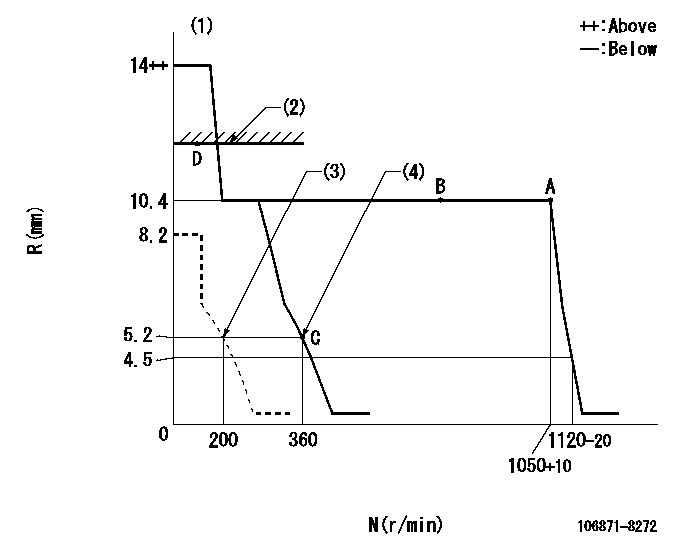
Injection quantity adjustment
Adjusting point
A
Rack position
10.4
Pump speed
r/min
1050
1050
1050
Average injection quantity
mm3/st.
162.4
160.4
164.4
Max. variation between cylinders
%
0
-2
2
Basic
*
Fixing the lever
*
Injection quantity adjustment_02
Adjusting point
C
Rack position
5.2+-0.5
Pump speed
r/min
360
360
360
Average injection quantity
mm3/st.
13
10
16
Max. variation between cylinders
%
0
-15
15
Fixing the rack
*
Injection quantity adjustment_03
Adjusting point
D
Rack position
-
Pump speed
r/min
100
100
100
Average injection quantity
mm3/st.
150
150
170
Fixing the lever
*
Timer adjustment
Pump speed
r/min
1050++
Advance angle
deg.
0
0
0
Remarks
Do not advance until starting N = 1050.
Do not advance until starting N = 1050.
Timer adjustment_02
Pump speed
r/min
1050
Advance angle
deg.
0.3
Timer adjustment_03
Pump speed
r/min
-
Advance angle
deg.
0.5
0.5
0.5
Remarks
Measure the actual speed, stop
Measure the actual speed, stop
Test data Ex:
Governor adjustment
N:Pump speed
R:Rack position (mm)
(1)Target notch: K
(2)RACK LIMIT
(3)Set idle sub-spring
(4)Main spring setting
----------
K=4
----------
----------
K=4
----------
Speed control lever angle
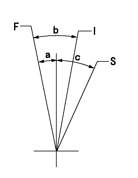
F:Full speed
I:Idle
S:Stop
----------
----------
a=2deg+-5deg b=25deg+-5deg c=(35deg)
----------
----------
a=2deg+-5deg b=25deg+-5deg c=(35deg)
Stop lever angle
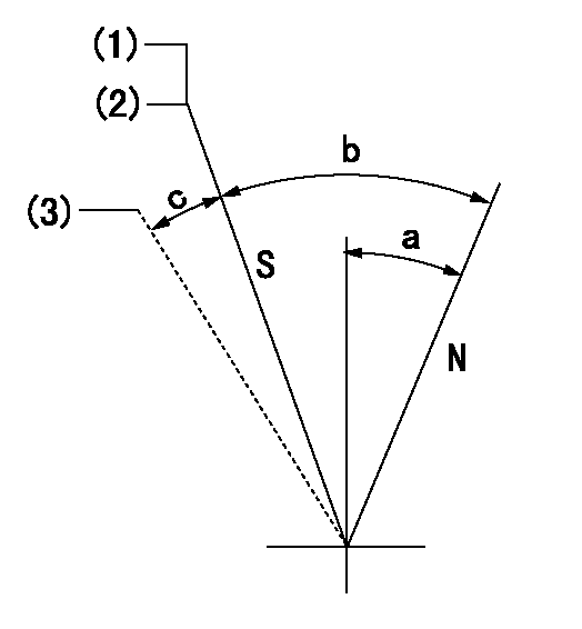
N:Pump normal
S:Stop the pump.
(1)At delivery
(2)Contacts inner stopper. Rack position aa or less, speed = bb
(3)Contacts outer stopper.
----------
aa=4.7mm bb=0r/min
----------
a=26.5deg+-5deg b=53deg+-5deg c=(11deg)
----------
aa=4.7mm bb=0r/min
----------
a=26.5deg+-5deg b=53deg+-5deg c=(11deg)
Timing setting

(1)Pump vertical direction
(2)Coupling's key groove position at No 1 cylinder's beginning of injection
(3)-
(4)-
----------
----------
a=(80deg)
----------
----------
a=(80deg)
Information:
TIMING PIN HOLE PLUG (Typical Example)
1. Plug.2. Rotate the crankshaft CLOCKWISE (as viewed from front of engine) until the timing pin drops into the timing slot in the fuel injection pump camshaft.3. Disconnect wire (2) from fuel shut off solenoid.4. Remove the tachometer drive adapter housing (3).
WIRE AND HOUSING (Typical Example)
2. Wire. 3. Tachometer drive adapter housing.5. Use ratchet (4) and socket (5) to remove the tachometer drive adapter shaft.
REMOVING SHAFT
4. 8H8572 Ratchet. 5. 9S5031 Deep Well Socket.6. Using puller group (6), thread the 9S8528 Bolt Assembly into the camshaft. Do not force the bolt assembly. It should thread easily. Install the 9S8527 Bolt by threading it into the gear carrier or adapter. Then tighten the 9S8527 Bolt with a wrench until the gear carrier or adapter "pops" loose. Remove the 9S8520 Puller Group.
LOOSENING CAMSHAFT DRIVE GEAR
6. 9S8520 Puller Group.7. Remove the plug from the timing hole (8) in the front cover and insert bolt (7). The cover retaining bolt from hole (9) may be used.8. Rotate crankshaft CLOCKWISE (as viewed from front of engine) until bolt (7) threads into the timing gear and is centered in timing hole (8). With timing pin in slot in fuel pump camshaft and the bolt (7) through the front cover and threaded into the timing gear, the fuel injection pump camshaft is timed to the engine.
INSTALLING BOLT
7. 1D4539 Bolt [5/16 in. - 18 NC, 2.5 in. (63.5 mm) long]. 8. Timing hole. 9. Hole.9. Remove the fuel injection pump housing retaining bolts (10).
RETAINING BOLTS (Typical Example)
10. Retaining bolts (three).
REMOVING HOUSING (Typical Example)10. Attach a hoist and remove the fuel injection pump housing and governor as a unit, the weight is approx. 55 lbs. (23 kg).Install Fuel Injection Pump Housing and Governor
1. Attach a hoist and install the fuel injection pump housing and governor as a unit. Install the fuel injection pump housing retaining bolts.2. Install the tachometer drive adapter shaft and tighten shaft retaining nut to 32 2 lb. ft. (4.4 0.3 mkg).3. To check timing remove the timing pin and the bolt. Rotate the crankshaft two revolutions CLOCKWISE (as viewed from front of engine) and install the timing pin and bolt back in place. If the timing pin or bolt can not be installed, the fuel injection pump camshaft must be retimed.4. Remove the bolt (7) from the timing gear and install in hole (9). Install the plug into timing hole (8).5. Remove the timing pin from the timing slot in the fuel injection pump camshaft and install the plug in the timing hole.6. Install the tachometer drive adapter housing. Connect the wire to the fuel shut off solenoid.
Have questions with 106871-8272?
Group cross 106871-8272 ZEXEL
Hino
106871-8272
9 400 618 263
220203193A
INJECTION-PUMP ASSEMBLY
EF750-TI
EF750-TI