Information injection-pump assembly
ZEXEL
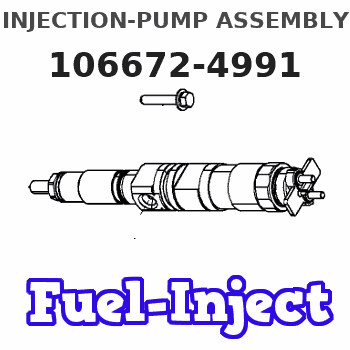
106672-4991
1066724991
Rating:
Service parts 106672-4991 INJECTION-PUMP ASSEMBLY:
1.
_
5.
AUTOM. ADVANCE MECHANIS
7.
COUPLING PLATE
8.
_
9.
_
10.
NOZZLE AND HOLDER ASSY
11.
Nozzle and Holder
12.
Open Pre:MPa(Kqf/cm2)
13.
NOZZLE-HOLDER
14.
NOZZLE
15.
NOZZLE SET
Include in #1:
106672-4991
as INJECTION-PUMP ASSEMBLY
Cross reference number
ZEXEL
106672-4991
1066724991
Zexel num
Bosch num
Firm num
Name
106672-4991
INJECTION-PUMP ASSEMBLY
Calibration Data:
Adjustment conditions
Test oil
1404 Test oil ISO4113 or {SAEJ967d}
1404 Test oil ISO4113 or {SAEJ967d}
Test oil temperature
degC
40
40
45
Nozzle and nozzle holder
105780-8140
Bosch type code
EF8511/9A
Nozzle
105780-0000
Bosch type code
DN12SD12T
Nozzle holder
105780-2080
Bosch type code
EF8511/9
Opening pressure
MPa
17.2
Opening pressure
kgf/cm2
175
Injection pipe
Outer diameter - inner diameter - length (mm) mm 8-3-600
Outer diameter - inner diameter - length (mm) mm 8-3-600
Overflow valve
131425-0120
Overflow valve opening pressure
kPa
157
123
191
Overflow valve opening pressure
kgf/cm2
1.6
1.25
1.95
Tester oil delivery pressure
kPa
157
157
157
Tester oil delivery pressure
kgf/cm2
1.6
1.6
1.6
Direction of rotation (viewed from drive side)
Left L
Left L
Injection timing adjustment
Direction of rotation (viewed from drive side)
Left L
Left L
Injection order
1-4-2-6-
3-5
Pre-stroke
mm
3.9
3.85
3.95
Beginning of injection position
Governor side NO.1
Governor side NO.1
Difference between angles 1
Cal 1-4 deg. 60 59.5 60.5
Cal 1-4 deg. 60 59.5 60.5
Difference between angles 2
Cyl.1-2 deg. 120 119.5 120.5
Cyl.1-2 deg. 120 119.5 120.5
Difference between angles 3
Cal 1-6 deg. 180 179.5 180.5
Cal 1-6 deg. 180 179.5 180.5
Difference between angles 4
Cal 1-3 deg. 240 239.5 240.5
Cal 1-3 deg. 240 239.5 240.5
Difference between angles 5
Cal 1-5 deg. 300 299.5 300.5
Cal 1-5 deg. 300 299.5 300.5
Injection quantity adjustment
Adjusting point
A
Rack position
14.4
Pump speed
r/min
750
750
750
Average injection quantity
mm3/st.
226.7
221.7
231.7
Max. variation between cylinders
%
0
-3
3
Basic
*
Fixing the rack
*
Injection quantity adjustment_02
Adjusting point
B
Rack position
13.6
Pump speed
r/min
900
900
900
Average injection quantity
mm3/st.
210.9
205.9
215.9
Max. variation between cylinders
%
0
-4
4
Fixing the rack
*
Injection quantity adjustment_03
Adjusting point
C
Rack position
7.1+-0.5
Pump speed
r/min
250
250
250
Average injection quantity
mm3/st.
30
27
33
Max. variation between cylinders
%
0
-10
10
Fixing the rack
*
Remarks
Adjust only variation between cylinders; adjust governor according to governor specifications.
Adjust only variation between cylinders; adjust governor according to governor specifications.
Test data Ex:
Governor adjustment
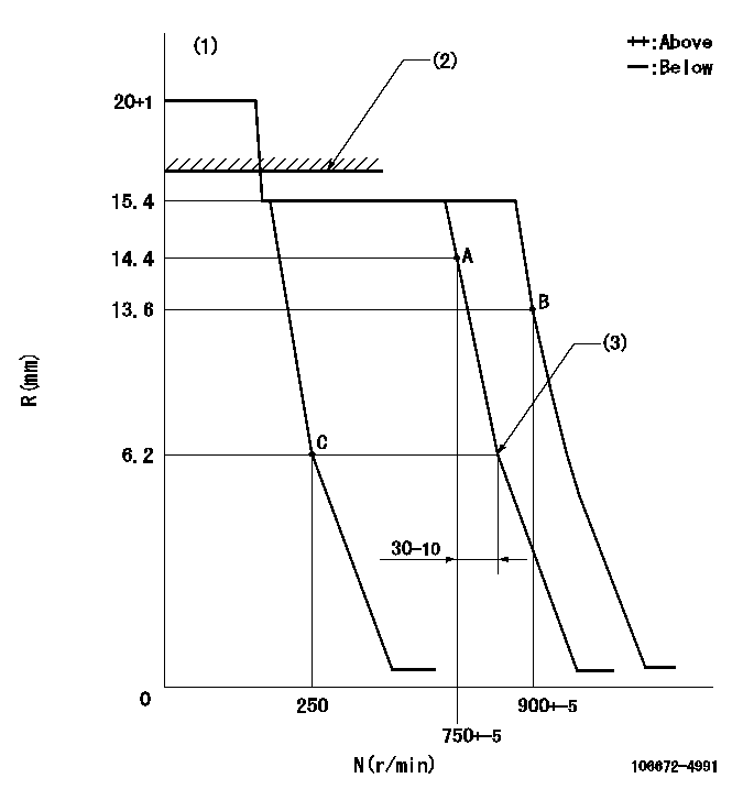
N:Pump speed
R:Rack position (mm)
(1)Target notch: K
(2)RACK LIMIT: RAL
(3)Idle sub spring setting: L1.
----------
K=5 RAL=16.4+0.2mm L1=6.2-0.5mm
----------
----------
K=5 RAL=16.4+0.2mm L1=6.2-0.5mm
----------
Speed control lever angle
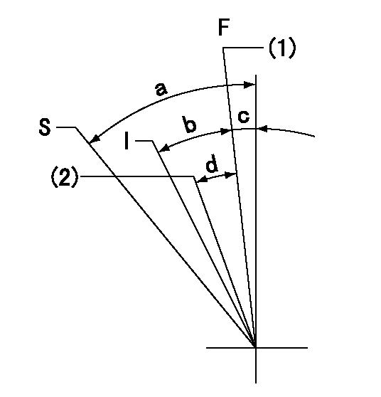
F:Full speed
I:Idle
S:Stop
(1)Speed set at aa (setting at shipping)
(2)Set the pump speed at bb.
----------
aa=900r/min bb=750r/min
----------
a=52deg+-3deg b=(32deg)+-5deg c=(10deg)+-5deg d=(8deg)+-5deg
----------
aa=900r/min bb=750r/min
----------
a=52deg+-3deg b=(32deg)+-5deg c=(10deg)+-5deg d=(8deg)+-5deg
Stop lever angle

N:Pump normal
S:Stop the pump.
----------
----------
a=36deg+-5deg b=53deg+-5deg
----------
----------
a=36deg+-5deg b=53deg+-5deg
Timing setting

(1)Pump vertical direction
(2)Coupling's key groove position at No 1 cylinder's beginning of injection
(3)B.T.D.C.: aa
(4)-
----------
aa=16deg
----------
a=(6deg)
----------
aa=16deg
----------
a=(6deg)
Information:
Start By:a. remove pistons1. Drain the coolant from the cylinder block.2. Put covers on the journals of the crankshaft for protection from dirt or water. 3. Remove cylinder liners (1) with Tool (A).4. Remove the O-ring seals and filler band from each of the cylinder liners.Install Cylinder Liners
1. Clean cylinder liners (3) and the liner bores in the cylinder block.2. Install the cylinder liners in the block without the O-ring seals or filler bands.3. Check the cylinder liner projection as follows:a. Install the S1589 Bolts (2) and 1S379 Washers of Tool (B) on the cylinder block next to each liner. Tighten the bolts evenly, in four steps: 14 N m (10 lb ft), 35 N m (25 lb ft), 70 N m (52 lb ft) and 95 N m (70 lb ft).b. Put the adapter plate on top of the liner, and install the remainder of Tool (B). Tighten the 1D4595 Bolts (1) evenly in four steps: 7 N m (5 lb ft), 20 N m (15 lb ft), 35 N m (25 lb ft) and 70 N m (52 lb ft).c. Check to be sure the distance from the bottom edge of the crossbar to the top of the cylinder block is the same on both sides of the liner.d. Check the cylinder liner projection with Tool (C) at four locations around the liner.e. Liner projection must be 0.033 to 0.175 mm (.0013 to .0069 in). Measurements on the same liner must not be different by more than 0.05 mm (.002 in). Average measurements between liners next to each other must not be different by more than 0.05 mm (.002 in). The maximum permissible difference between average projection of all cylinder liners is 0.10 mm (.004 in). If the liner is turned in the bore, it can make a difference in the liner projection.4. If the projection is not 0.033 to 0.175 mm (.0013 to .0069 in), check the thickness of the following parts: spacer plate, spacer plate gasket and cylinder liner flange. The thickness of the spacer plate must be 9.970 0.025 mm (.3925 .0010 in). The thickness of the spacer plate gasket must be 0.208 0.025 mm (.0082 .0010 in). The thickness of the cylinder liner flange must be 10.282 0.020 mm (.4048 .0008 in). If the liner projection changes from point to point around the liner, turn the liner to a new position in the bore. If the liner projection is still not to specifications, move the liner to a different bore.5. When the cylinder projection is correct, put an alignment mark on the liner and block so the liner can be installed in the same position from which it was removed. Cylinder liner projection can be adjusted by the removal of material from (machining) the contact face of the cylinder block with the use of the 8S3140 Cylinder Block Counterboring Tool Arrangement. Machine to a minimum depth of 0.76 mm (.030 in) and to a maximum
1. Clean cylinder liners (3) and the liner bores in the cylinder block.2. Install the cylinder liners in the block without the O-ring seals or filler bands.3. Check the cylinder liner projection as follows:a. Install the S1589 Bolts (2) and 1S379 Washers of Tool (B) on the cylinder block next to each liner. Tighten the bolts evenly, in four steps: 14 N m (10 lb ft), 35 N m (25 lb ft), 70 N m (52 lb ft) and 95 N m (70 lb ft).b. Put the adapter plate on top of the liner, and install the remainder of Tool (B). Tighten the 1D4595 Bolts (1) evenly in four steps: 7 N m (5 lb ft), 20 N m (15 lb ft), 35 N m (25 lb ft) and 70 N m (52 lb ft).c. Check to be sure the distance from the bottom edge of the crossbar to the top of the cylinder block is the same on both sides of the liner.d. Check the cylinder liner projection with Tool (C) at four locations around the liner.e. Liner projection must be 0.033 to 0.175 mm (.0013 to .0069 in). Measurements on the same liner must not be different by more than 0.05 mm (.002 in). Average measurements between liners next to each other must not be different by more than 0.05 mm (.002 in). The maximum permissible difference between average projection of all cylinder liners is 0.10 mm (.004 in). If the liner is turned in the bore, it can make a difference in the liner projection.4. If the projection is not 0.033 to 0.175 mm (.0013 to .0069 in), check the thickness of the following parts: spacer plate, spacer plate gasket and cylinder liner flange. The thickness of the spacer plate must be 9.970 0.025 mm (.3925 .0010 in). The thickness of the spacer plate gasket must be 0.208 0.025 mm (.0082 .0010 in). The thickness of the cylinder liner flange must be 10.282 0.020 mm (.4048 .0008 in). If the liner projection changes from point to point around the liner, turn the liner to a new position in the bore. If the liner projection is still not to specifications, move the liner to a different bore.5. When the cylinder projection is correct, put an alignment mark on the liner and block so the liner can be installed in the same position from which it was removed. Cylinder liner projection can be adjusted by the removal of material from (machining) the contact face of the cylinder block with the use of the 8S3140 Cylinder Block Counterboring Tool Arrangement. Machine to a minimum depth of 0.76 mm (.030 in) and to a maximum
Have questions with 106672-4991?
Group cross 106672-4991 ZEXEL
Yanmar
Yanmar
Kubota
Daihatsu
Daihatsu
Komatsu
Komatsu
Niigata-Urawa
106672-4991
INJECTION-PUMP ASSEMBLY