Information injection-pump assembly
ZEXEL
106672-4990
1066724990
NIIGATA-URAWA
W2B47051B
w2b47051b
Rating:
Cross reference number
ZEXEL
106672-4990
1066724990
NIIGATA-URAWA
W2B47051B
w2b47051b
Zexel num
Bosch num
Firm num
Name
Calibration Data:
Adjustment conditions
Test oil
1404 Test oil ISO4113 or {SAEJ967d}
1404 Test oil ISO4113 or {SAEJ967d}
Test oil temperature
degC
40
40
45
Nozzle and nozzle holder
105780-8140
Bosch type code
EF8511/9A
Nozzle
105780-0000
Bosch type code
DN12SD12T
Nozzle holder
105780-2080
Bosch type code
EF8511/9
Opening pressure
MPa
17.2
Opening pressure
kgf/cm2
175
Injection pipe
Outer diameter - inner diameter - length (mm) mm 8-3-600
Outer diameter - inner diameter - length (mm) mm 8-3-600
Overflow valve
134424-1420
Overflow valve opening pressure
kPa
162
147
177
Overflow valve opening pressure
kgf/cm2
1.65
1.5
1.8
Tester oil delivery pressure
kPa
157
157
157
Tester oil delivery pressure
kgf/cm2
1.6
1.6
1.6
Direction of rotation (viewed from drive side)
Left L
Left L
Injection timing adjustment
Direction of rotation (viewed from drive side)
Left L
Left L
Injection order
1-4-2-6-
3-5
Pre-stroke
mm
3.9
3.85
3.95
Beginning of injection position
Governor side NO.1
Governor side NO.1
Difference between angles 1
Cal 1-4 deg. 60 59.5 60.5
Cal 1-4 deg. 60 59.5 60.5
Difference between angles 2
Cyl.1-2 deg. 120 119.5 120.5
Cyl.1-2 deg. 120 119.5 120.5
Difference between angles 3
Cal 1-6 deg. 180 179.5 180.5
Cal 1-6 deg. 180 179.5 180.5
Difference between angles 4
Cal 1-3 deg. 240 239.5 240.5
Cal 1-3 deg. 240 239.5 240.5
Difference between angles 5
Cal 1-5 deg. 300 299.5 300.5
Cal 1-5 deg. 300 299.5 300.5
Injection quantity adjustment
Adjusting point
A
Rack position
14.4
Pump speed
r/min
750
750
750
Average injection quantity
mm3/st.
226.7
221.7
231.7
Max. variation between cylinders
%
0
-3
3
Basic
*
Fixing the rack
*
Injection quantity adjustment_02
Adjusting point
B
Rack position
13.6
Pump speed
r/min
900
900
900
Average injection quantity
mm3/st.
210.9
205.9
215.9
Max. variation between cylinders
%
0
-4
4
Fixing the rack
*
Injection quantity adjustment_03
Adjusting point
C
Rack position
7.1+-0.5
Pump speed
r/min
250
250
250
Average injection quantity
mm3/st.
30
27
33
Max. variation between cylinders
%
0
-10
10
Fixing the rack
*
Remarks
Adjust only variation between cylinders; adjust governor according to governor specifications.
Adjust only variation between cylinders; adjust governor according to governor specifications.
Test data Ex:
Governor adjustment
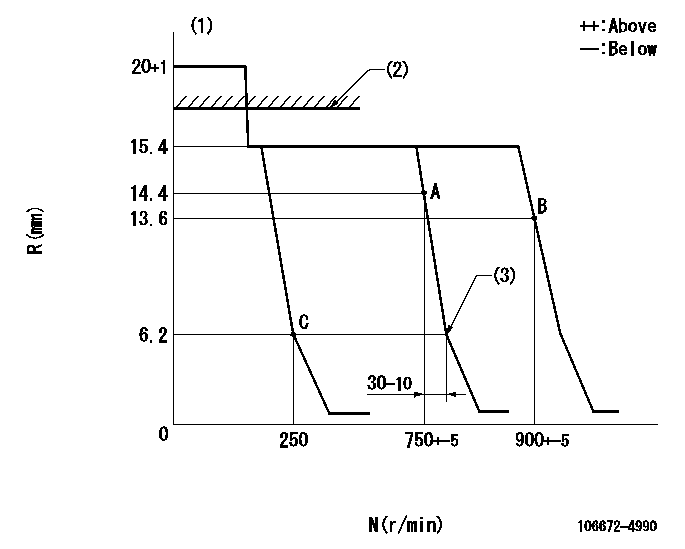
N:Pump speed
R:Rack position (mm)
(1)Target notch: K
(2)RACK LIMIT: RAL
(3)Idle sub spring setting: L1.
----------
K=5 RAL=16.4+0.2mm L1=6.2-0.5mm
----------
----------
K=5 RAL=16.4+0.2mm L1=6.2-0.5mm
----------
Speed control lever angle
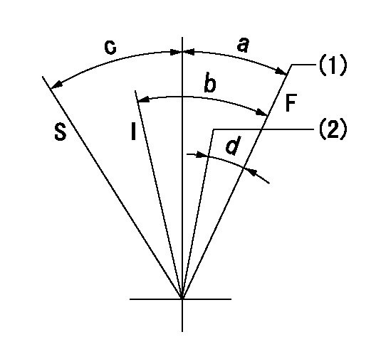
F:Full speed
I:Idle
S:Stop
(1)Speed set at aa (setting at shipping)
(2)Set the pump speed at bb.
----------
aa=900r/min bb=750r/min
----------
a=(10deg)+-5deg b=(32deg)+-5deg c=(32deg)+-3deg d=(8deg)+-5deg
----------
aa=900r/min bb=750r/min
----------
a=(10deg)+-5deg b=(32deg)+-5deg c=(32deg)+-3deg d=(8deg)+-5deg
Stop lever angle
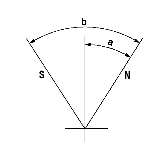
N:Pump normal
S:Stop the pump.
----------
----------
a=42deg+-5deg b=82deg+-5deg
----------
----------
a=42deg+-5deg b=82deg+-5deg
Timing setting

(1)Pump vertical direction
(2)Coupling's key groove position at No 1 cylinder's beginning of injection
(3)B.T.D.C.: aa
(4)-
----------
aa=16deg
----------
a=(6deg)
----------
aa=16deg
----------
a=(6deg)
Information:
2. Turn the crankshaft until two of the pistons are at bottom center. Remove the nuts and bolts (1) from the connecting rods that are at bottom center. Remove connecting rod caps (2). Put identification marks on them for installation purposes.
Do not let the connecting rods hit the crankshaft or the bottom edge of the cylinder liners when the pistons are removed.
3. Push the connecting rods and pistons away from the crankshaft until the piston rings are out of the cylinder liners. Remove the two pistons from the engine.4. Keep each connecting rod cap with its respective connecting rod and piston. Put identification marks on each piston as to its location in the engine.5. Do Steps 1 through 4 for the removal of the remaining pistons.Install Pistons & Connecting Rods
1. Turn the crankshaft until the bearing journals for the pistons to be installed are at bottom center.2. Put clean engine oil on the crankshaft journals and on the inside of the cylinder liners. Put clean engine oil on the piston rings and the connecting rod bearings.3. Move the piston rings on the pistons until the ring openings are approximately 90° apart. 4. Put the piston in the cylinder liner with the "V" mark on the piston in alignment with the "V" mark on the cylinder block. Put Tool (A) in position on the cylinder block and compress the piston rings.5. Push the piston into the cylinder liner and out of the ring compressor. 6. Pull the connecting rod into position on the crankshaft as shown. Install connecting rod bolts (1) in the connecting rods.7. Put clean engine oil on the lower half of the connecting rod bearing. Put 2P2506 Thread Lubricant on the bolt threads and on the surfaces of the nuts that make contact with the connecting rod caps.
When the connecting rod caps are installed, make sure the number on the side of the cap is next to and respective with the number on the side of the connecting rod.
8. Install connecting rod caps (2) and the nuts that hold them. Tighten the nuts to a torque of 40 4 N m (30 3 lb ft). Put a mark on each nut as to its location. Tighten them 90° 5° more.9. Do Steps 1 through 8 for the remainder of the pistons.End By:a. install oil pumpb. install oil pan platec. install cylinder head assembly and spacer plateDisassemble Pistons & Connecting Rods
Start By:a. remove pistons and connecting rods 1. Remove the rings from the pistons with Tool (A). 2. Remove retaining ring (3), piston pin (1) and connecting rod (2) from the piston.3. Remove the bearings from the crankshaft end of the connecting rod.4. See Use Of Piston Pin Bearing Removal And Installation Tools, Special Instructions, Form No. SMHS7295-02 for more information about removal and installation of piston pin bearings. Be sure to remove the bearings from the crankshaft end of connecting rod.5. Heat the connecting rod in an oven to a temperature of 176