Information injection-pump assembly
BOSCH
9 460 614 072
9460614072
ZEXEL
104746-5051
1047465051
ISUZU
8972530221
8972530221

Rating:
Compare Prices: .
As an associate, we earn commssions on qualifying purchases through the links below

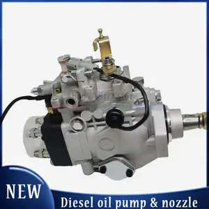
Fits Compatible with Isuzu Engine 4JG2 8-97253022-1 Fuel Injector Pump 104746-5051 8972530221
EWAIDI Part Number: 8-97253022-1 104746-5051 8972530221 Note: Please check the fitment carefully before purchase. Or just tell us the part number you need. || Application: Fits For Isuzu Engine 4JG2 || Part Number: 4JG2 is a crucial code that identifies the unique characteristics and specs of an engine component. It helps in accurately ordering the right part for maintenance and repair. Referring to this number ensures compatibility, efficiency, and optimal performance of the engine system, promoting longevity. || The Fuel Injection Pump is vital for delivering the correct amount of fuel to the engine, enhancing fuel efficiency, performance, and reducing emissions. It regulates fuel flow accurately, improving consumption. Proper maintenance is crucial for the engine's health and vehicle's reliability. || Included in the package is one piece of the Fuel Injector Pump with the part number 8-97253022-1, which is also known as 104746-5051 or 8972530221.
EWAIDI Part Number: 8-97253022-1 104746-5051 8972530221 Note: Please check the fitment carefully before purchase. Or just tell us the part number you need. || Application: Fits For Isuzu Engine 4JG2 || Part Number: 4JG2 is a crucial code that identifies the unique characteristics and specs of an engine component. It helps in accurately ordering the right part for maintenance and repair. Referring to this number ensures compatibility, efficiency, and optimal performance of the engine system, promoting longevity. || The Fuel Injection Pump is vital for delivering the correct amount of fuel to the engine, enhancing fuel efficiency, performance, and reducing emissions. It regulates fuel flow accurately, improving consumption. Proper maintenance is crucial for the engine's health and vehicle's reliability. || Included in the package is one piece of the Fuel Injector Pump with the part number 8-97253022-1, which is also known as 104746-5051 or 8972530221.

You can express buy:
USD 653.93
19-05-2025
19-05-2025
Factory Price New Fuel Injection Pump NP-VE4/11F1200LNP2293 8-97253022-1 9460614072 104746-5051 8972530221 For Isuzu 4JG2
Images:
USD 426.22

[19-May-2025]
USD 419.02

[14-Jun-2025]
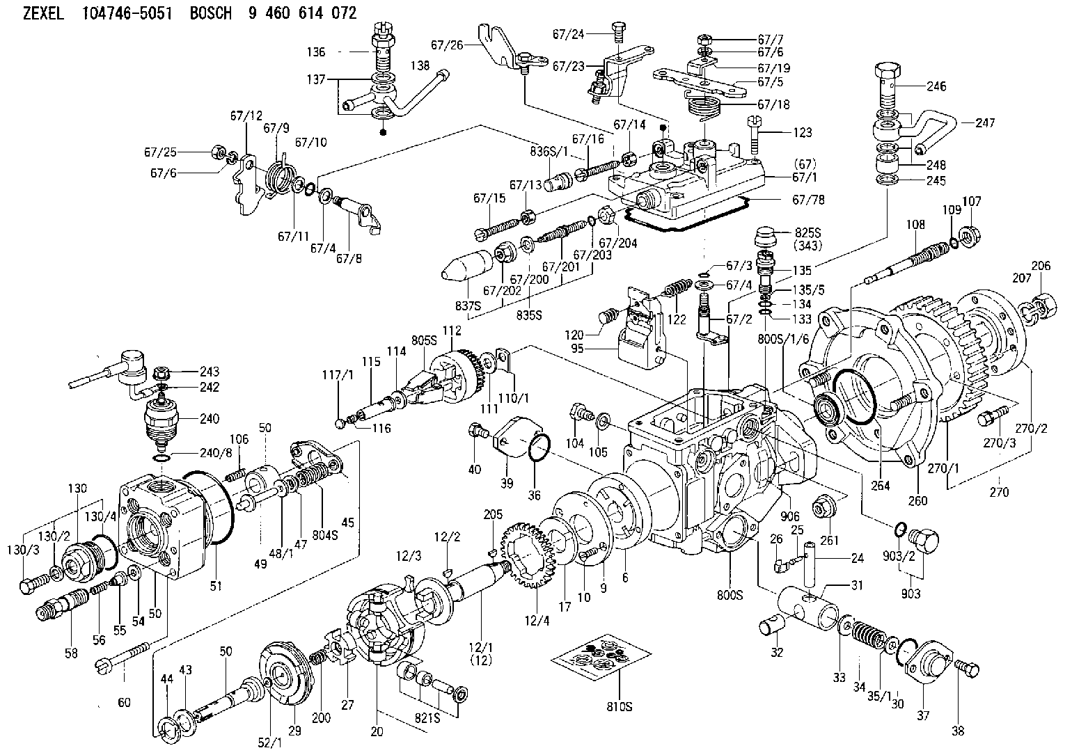
Components :
| 0. | INJECTION-PUMP ASSEMBLY | 104746-5051 |
| 1. | _ | |
| 2. | FUEL INJECTION PUMP | 104646-5051 |
| 3. | NUMBER PLATE | |
| 4. | _ | |
| 5. | CAPSULE | |
| 6. | ADJUSTING DEVICE | |
| 7. | NOZZLE AND HOLDER ASSY | 105158-2322 |
| 8. | Nozzle and Holder | 8-97079-653-0 |
| 9. | Open Pre:MPa(Kqf/cm2) | 14.7{150} |
| 10. | NOZZLE-HOLDER | 105088-1140 |
| 11. | NOZZLE | 105007-1310 |
Scheme ###:
| 1/6. | [1] | 146601-0700 | PACKING RING |
| 6. | [1] | 146100-0120 | SUPPLY PUMP |
| 9. | [1] | 146103-0000 | COVER |
| 10. | [2] | 139104-0000 | FLAT-HEAD SCREW |
| 12. | [1] | 146200-0320 | DRIVE SHAFT |
| 12/1. | [1] | 146200-0300 | DRIVE SHAFT |
| 12/2. | [1] | 146201-0000 | WOODRUFF KEY |
| 12/3. | [2] | 146202-0100 | DAMPER |
| 12/4. | [1] | 146203-0000 | TOOTHED GEAR |
| 17. | [1] | 146204-0000 | PLAIN WASHER |
| 20. | [1] | 146210-1720 | ROLLER SET |
| 24. | [1] | 146303-0000 | BEARING PIN |
| 25. | [1] | 146304-0000 | BEARING PIN |
| 26. | [1] | 146305-0000 | CLAMPING BAND |
| 27. | [1] | 146205-0000 | SLOTTED WASHER |
| 29. | [1] | 146220-0020 | CAM PLATE |
| 30. | [1] | 146600-0800 | O-RING |
| 31. | [1] | 146300-4400 | PUMP PLUNGER |
| 32. | [1] | 146301-0000 | SLIDING PIECE |
| 33. | [1] | 146603-0700 | SHIM D17.5&7.5T0.60 |
| 34. | [1] | 146302-4200 | COMPRESSION SPRING |
| 34B. | [1] | 146302-4800 | COMPRESSION SPRING |
| 34C. | [1] | 146306-1100 | COMPRESSION SPRING |
| 35/1. | [0] | 146603-0700 | SHIM D17.5&7.5T0.60 |
| 35/1. | [0] | 146603-0800 | SHIM D17.5&7.5T0.70 |
| 35/1. | [0] | 146603-0900 | SHIM D17.5&7.5T0.90 |
| 35/1. | [0] | 146603-1000 | SHIM D17.5&7.5T1.00 |
| 35/1. | [0] | 146603-1100 | SHIM D17.5&7.5T1.20 |
| 35/1. | [0] | 146603-3600 | SHIM D17.5&7.5T2.40 |
| 36. | [1] | 146600-0800 | O-RING |
| 37. | [1] | 146310-0700 | COVER |
| 38. | [2] | 146620-5000 | BLEEDER SCREW |
| 39. | [1] | 146310-0100 | COVER |
| 40. | [2] | 146620-5000 | BLEEDER SCREW |
| 43. | [1] | 146230-0000 | SHIM |
| 44. | [1] | 146230-0100 | PLAIN WASHER |
| 45. | [1] | 146231-0001 | SLOTTED WASHER |
| 47. | [2] | 146233-0000 | SLOTTED WASHER |
| 48/1. | [1] | 146603-0000 | SHIM D17.0&5.2T0.50 |
| 48/1. | [1] | 146603-0100 | SHIM D17.0&5.2T0.80 |
| 48/1. | [1] | 146603-0200 | SHIM D17.0&5.2T1.00 |
| 48/1. | [1] | 146603-0300 | SHIM D17.0&5.2T1.20 |
| 48/1. | [1] | 146603-0400 | SHIM D17.0&5.2T1.50 |
| 48/1. | [1] | 146603-0500 | SHIM D17.0&5.2T1.80 |
| 48/1. | [1] | 146603-0600 | SHIM D17.0&5.2T2.00 |
| 48/1. | [1] | 146690-1400 | SHIM D17&5.2T0.9 |
| 48/1. | [1] | 146690-1500 | SHIM D17&5.2T1.1 |
| 48/1. | [1] | 146690-1600 | SHIM D17&5.2T1.3 |
| 48/1. | [1] | 146690-1700 | SHIM D17&5.2T1.4 |
| 48/1. | [1] | 146690-1800 | SHIM D17&5.2T1.6 |
| 48/1. | [1] | 146690-1900 | SHIM D17&5.2T1.7 |
| 48/1. | [1] | 146690-5800 | SHIM D17&5.2T2.1 |
| 48/1. | [1] | 146690-5900 | SHIM D17&5.2T2.2 |
| 48/1. | [1] | 146690-6000 | SHIM D17&5.2T2.3 |
| 48/1. | [1] | 146690-6100 | SHIM D17&5.2T2.4 |
| 48/1. | [1] | 146690-6200 | SHIM D17&5.2T2.5 |
| 48/1. | [1] | 146690-6300 | SHIM D17&5.2T2.6 |
| 48/1. | [1] | 146690-6400 | SHIM D17&5.2T2.7 |
| 48/1. | [1] | 146690-6500 | SHIM D17&5.2T2.8 |
| 48/1. | [1] | 146690-6600 | SHIM D17&5.2T2.9 |
| 48/1. | [1] | 146690-6700 | SHIM D17&5.2T3.0 |
| 48/1. | [1] | 146690-6800 | SHIM D17&5.2T3.1 |
| 48/1. | [1] | 146690-6900 | SHIM D17&5.2T3.2 |
| 48/1. | [1] | 146690-7000 | SHIM D17&5.2T3.3 |
| 48/1. | [1] | 146690-7100 | SHIM D17&5.2T3.4 |
| 48/1. | [1] | 146690-7200 | SHIM D17&5.2T0.4 |
| 48/1. | [1] | 146690-7300 | SHIM D17&5.2T0.6 |
| 48/1. | [1] | 146690-7400 | SHIM D17&5.2T0.7 |
| 48/1. | [1] | 146690-7500 | SHIM D17&5.2T1.9 |
| 48/1. | [1] | 146690-7800 | SHIM D17&5.2T0.2 |
| 49. | [2] | 146234-0500 | GUIDE PIN |
| 50. | [1] | 146403-4820 | HYDRAULIC HEAD |
| 50. | [1] | 146403-4820 | HYDRAULIC HEAD |
| 50. | [1] | 146403-4820 | HYDRAULIC HEAD |
| 51. | [1] | 146600-0000 | O-RING |
| 52/1. | [1] | 146420-0000 | SHIM D9.5&3.0T1.90 |
| 52/1. | [1] | 146420-0100 | SHIM D9.5&3.0T1.92 |
| 52/1. | [1] | 146420-0200 | SHIM D9.5&3.0T1.94 |
| 52/1. | [1] | 146420-0300 | SHIM D9.5&3.0T1.96 |
| 52/1. | [1] | 146420-0400 | SHIM D9.5&3.0T1.98 |
| 52/1. | [1] | 146420-0500 | SHIM D9.5&3.0T2.00 |
| 52/1. | [1] | 146420-0600 | SHIM D9.5&3.0T2.02 |
| 52/1. | [1] | 146420-0700 | SHIM D9.5&3.0T2.04 |
| 52/1. | [1] | 146420-0800 | SHIM D9.5&3.0T2.06 |
| 52/1. | [1] | 146420-0900 | SHIM D9.5&3.0T2.08 |
| 52/1. | [1] | 146420-1000 | SHIM D9.5&3.0T2.10 |
| 52/1. | [1] | 146420-1100 | SHIM D9.5&3.0T2.12 |
| 52/1. | [1] | 146420-1200 | SHIM D9.5&3.0T2.14 |
| 52/1. | [1] | 146420-1300 | SHIM D9.5&3.0T2.16 |
| 52/1. | [1] | 146420-1400 | SHIM D9.5&3.0T2.18 |
| 52/1. | [1] | 146420-1500 | SHIM D9.5&3.0T2.20 |
| 52/1. | [1] | 146420-1600 | SHIM D9.5&3.0T2.22 |
| 52/1. | [1] | 146420-1700 | SHIM D9.5&3.0T2.24 |
| 52/1. | [1] | 146420-1800 | SHIM D9.5&3.0T2.26 |
| 52/1. | [1] | 146420-1900 | SHIM D9.5&3.0T2.28 |
| 52/1. | [1] | 146420-2000 | SHIM D9.5&3.0T2.30 |
| 52/1. | [1] | 146420-2100 | SHIM D9.5&3.0T2.32 |
| 52/1. | [1] | 146420-2200 | SHIM D9.5&3.0T2.34 |
| 52/1. | [1] | 146420-2300 | SHIM D9.5&3.0T2.36 |
| 52/1. | [1] | 146420-2400 | SHIM D9.5&3.0T2.38 |
| 52/1. | [1] | 146420-2500 | SHIM D9.5&3.0T2.40 |
| 52/1. | [1] | 146420-2600 | SHIM D9.5&3.0T2.42 |
| 52/1. | [1] | 146420-2700 | SHIM D9.5&3.0T2.44 |
| 52/1. | [1] | 146420-2800 | SHIM D9.5&3.0T2.46 |
| 52/1. | [1] | 146420-2900 | SHIM D9.5&3.0T2.48 |
| 52/1. | [1] | 146420-3000 | SHIM D9.5&3.0T2.50 |
| 52/1. | [1] | 146420-3100 | SHIM D9.5&3.0T2.52 |
| 52/1. | [1] | 146420-3200 | SHIM D9.5&3.0T2.54 |
| 52/1. | [1] | 146420-3300 | SHIM D9.5&3.0T2.56 |
| 52/1. | [1] | 146420-3400 | SHIM D9.5&3.0T2.58 |
| 52/1. | [1] | 146420-3500 | SHIM D9.5&3.0T2.60 |
| 52/1. | [1] | 146420-3600 | SHIM D9.5&3.0T2.62 |
| 52/1. | [1] | 146420-3700 | SHIM D9.5&3.0T2.64 |
| 52/1. | [1] | 146420-3800 | SHIM D9.5&3.0T2.66 |
| 52/1. | [1] | 146420-3900 | SHIM D9.5&3.0T2.68 |
| 52/1. | [1] | 146420-4000 | SHIM D9.5&3.0T2.70 |
| 52/1. | [1] | 146420-4100 | SHIM D9.5&3.0T2.72 |
| 52/1. | [1] | 146420-4200 | SHIM D9.5&3.0T2.74 |
| 52/1. | [1] | 146420-4300 | SHIM D9.5&3.0T2.76 |
| 52/1. | [1] | 146420-4400 | SHIM D9.5&3.0T2.78 |
| 52/1. | [1] | 146420-4500 | SHIM D9.5&3.0T2.80 |
| 52/1. | [1] | 146420-4600 | SHIM D9.5&3.0T2.82 |
| 52/1. | [1] | 146420-4700 | SHIM D9.5&3.0T2.84 |
| 52/1. | [1] | 146420-4800 | SHIM D9.5&3.0T2.86 |
| 52/1. | [1] | 146420-4900 | SHIM D9.5&3.0T2.88 |
| 52/1. | [1] | 146420-5000 | SHIM D9.5&3.0T2.90 |
| 52/1. | [1] | 146420-5100 | SHIM D9.5&3.0T1.74 |
| 52/1. | [1] | 146420-5200 | SHIM D9.5&3.0T1.76 |
| 52/1. | [1] | 146420-5300 | SHIM D9.5&3.0T1.78 |
| 52/1. | [1] | 146420-5400 | SHIM D9.5&3.0T1.80 |
| 52/1. | [1] | 146420-5500 | SHIM D9.5&3.0T1.82 |
| 52/1. | [1] | 146420-5600 | SHIM D9.5&3.0T1.84 |
| 52/1. | [1] | 146420-5700 | SHIM D9.5&3.0T1.86 |
| 52/1. | [1] | 146420-5800 | SHIM D9.5&3.0T1.88 |
| 54. | [4] | 146433-0100 | GASKET D12&6.4T1.00 |
| 55. | [4] | 146430-0020 | DELIVERY-VALVE ASSEMBLY |
| 56. | [4] | 146432-0000 | COMPRESSION SPRING |
| 58. | [4] | 146440-0120 | FITTING |
| 60. | [4] | 139106-0100 | FLAT-HEAD SCREW |
| 67. | [1] | 146821-8320 | GOVERNOR COVER |
| 67/1. | [1] | 146508-1022 | GOVERNOR COVER |
| 67/2. | [1] | 146515-0320 | CONTROL SHAFT |
| 67/3. | [1] | 146600-0100 | O-RING |
| 67/4. | [2] | 139310-0200 | PLAIN WASHER |
| 67/4. | [2] | 139310-0200 | PLAIN WASHER |
| 67/5. | [1] | 146530-0000 | CONTROL LEVER |
| 67/5B. | [1] | 146530-0100 | CONTROL LEVER |
| 67/5C. | [1] | 146832-1500 | CONTROL LEVER |
| 67/5D. | [1] | 146832-1600 | CONTROL LEVER |
| 67/6. | [2] | 014110-6440 | LOCKING WASHER |
| 67/6. | [2] | 014110-6440 | LOCKING WASHER |
| 67/7. | [1] | 013020-6040 | UNION NUT M6P1H5 |
| 67/8. | [1] | 146515-0020 | LEVER SHAFT |
| 67/9. | [1] | 146587-4500 | COILED SPRING |
| 67/10. | [1] | 146600-0200 | O-RING |
| 67/11. | [1] | 146602-0100 | PLAIN WASHER D14&10.1T1.50 |
| 67/12. | [1] | 146540-1300 | CONTROL LEVER |
| 67/12B. | [1] | 146540-1400 | CONTROL LEVER |
| 67/13. | [1] | 146621-1700 | UNION NUT |
| 67/14. | [1] | 146621-1700 | UNION NUT |
| 67/15. | [1] | 146526-2800 | BLEEDER SCREW |
| 67/16. | [1] | 146526-2800 | BLEEDER SCREW |
| 67/18. | [1] | 146587-2000 | COILED SPRING |
| 67/19. | [1] | 146541-0000 | ANGLE PIECE |
| 67/23. | [1] | 146925-2520 | BRACKET |
| 67/24. | [2] | 139006-4500 | BLEEDER SCREW |
| 67/25. | [1] | 013020-6040 | UNION NUT M6P1H5 |
| 67/26. | [1] | 146925-2920 | BRACKET |
| 67/78. | [1] | 146600-4400 | SEAL RING |
| 67/200. | [1] | 139308-0300 | PLAIN WASHER |
| 67/201. | [1] | 146545-4600 | THREADED PIN |
| 67/201B. | [1] | 146545-4700 | THREADED PIN |
| 67/201C. | [1] | 146545-4800 | THREADED PIN |
| 67/202. | [1] | 146598-5000 | UNION NUT |
| 67/203. | [1] | 146600-1200 | O-RING |
| 67/204. | [1] | 146545-4500 | DAMPER |
| 95. | [1] | 146851-4920 | FULCRUM LEVER |
| 104. | [2] | 146568-0000 | SLOTTED SPRING PIN |
| 105. | [2] | 026508-1140 | GASKET D11.4&8.2T1 |
| 106. | [2] | 146588-0500 | COILED SPRING |
| 107. | [1] | 146569-0300 | UNION NUT |
| 108. | [1] | 146570-0100 | GOVERNOR SHAFT |
| 109. | [1] | 146600-0400 | O-RING |
| 110/1. | [1] | 146571-0000 | SHIM D20.2&8.3T1.05 |
| 110/1. | [1] | 146571-0100 | SHIM D20.2&8.3T1.25 |
| 110/1. | [1] | 146571-0200 | SHIM D20.2&8.3T1.45 |
| 110/1. | [1] | 146571-0300 | SHIM D20.2&8.3T1.65 |
| 110/1. | [1] | 146571-0400 | SHIM D20.2&8.3T1.85 |
| 110/1. | [1] | 146571-0500 | SHIM D20.2&8.3T1.15 |
| 110/1. | [1] | 146571-0600 | SHIM D20.2&8.3T1.35 |
| 110/1. | [1] | 146571-0700 | SHIM D20.2&8.3T1.55 |
| 110/1. | [1] | 146571-0800 | SHIM D20.2&8.3T1.75 |
| 111. | [1] | 146602-0600 | PLAIN WASHER D20&8.4T1.40 |
| 112. | [1] | 146572-0020 | FLYWEIGHT ASSEMBLY |
| 114. | [1] | 146602-2600 | PLAIN WASHER D34&13T1.0 |
| 115. | [1] | 146976-0700 | SLIDING SLEEVE |
| 116. | [1] | 146576-0400 | CAP |
| 117/1. | [1] | 146877-0820 | PLUG |
| 117/1. | [1] | 146877-0920 | PLUG |
| 117/1. | [1] | 146877-1020 | PLUG |
| 117/1. | [1] | 146877-1120 | PLUG |
| 117/1. | [1] | 146877-1220 | PLUG |
| 117/1. | [1] | 146877-1320 | PLUG |
| 117/1. | [1] | 146877-1420 | PLUG |
| 117/1. | [1] | 146877-1520 | PLUG |
| 117/1. | [1] | 146877-1620 | PLUG |
| 117/1. | [1] | 146877-1720 | PLUG |
| 117/1. | [1] | 146877-1820 | PLUG |
| 117/1. | [1] | 146877-1920 | PLUG |
| 117/1. | [1] | 146877-2020 | PLUG |
| 117/1. | [1] | 146877-2120 | PLUG |
| 117/1. | [1] | 146877-2220 | PLUG |
| 117/1. | [1] | 146877-2320 | PLUG |
| 117/1. | [1] | 146877-2420 | PLUG |
| 117/1. | [1] | 146877-2520 | PLUG |
| 117/1. | [1] | 146877-2620 | PLUG |
| 117/1. | [1] | 146877-2720 | PLUG |
| 117/1. | [1] | 146877-2820 | PLUG |
| 117/1. | [1] | 146877-2920 | PLUG |
| 117/1. | [1] | 146877-3020 | PLUG |
| 117/1. | [1] | 146877-3120 | PLUG |
| 117/1. | [1] | 146877-3220 | PLUG |
| 117/1. | [1] | 146877-3320 | PLUG |
| 117/1. | [1] | 146877-3420 | PLUG |
| 117/1. | [1] | 146877-3520 | PLUG |
| 117/1. | [1] | 146877-3620 | PLUG |
| 117/1. | [1] | 146877-3720 | PLUG |
| 117/1. | [1] | 146877-3820 | PLUG |
| 117/1. | [1] | 146877-3920 | PLUG |
| 117/1. | [1] | 146877-4020 | PLUG |
| 117/1. | [1] | 146877-4120 | PLUG |
| 117/1. | [1] | 146877-4220 | PLUG |
| 120. | [1] | 146879-5020 | RETAINING PIN |
| 122. | [1] | 146580-3700 | GOVERNOR SPRING |
| 123. | [4] | 139106-0200 | FLAT-HEAD SCREW |
| 130. | [1] | 146421-0020 | CAPSULE |
| 130/2. | [1] | 026508-1140 | GASKET D11.4&8.2T1 |
| 130/3. | [1] | 146422-0000 | BLEEDER SCREW |
| 130/4. | [1] | 146600-0500 | O-RING |
| 133. | [1] | 146600-0600 | O-RING |
| 134. | [1] | 146600-0700 | O-RING |
| 135. | [1] | 146110-1020 | CONTROL VALVE |
| 135/5. | [1] | 146114-0000 | SPRING WASHER |
| 136. | [1] | 146120-0120 | OVER FLOW VALVE |
| 137. | [2] | 139512-0500 | GASKET |
| 138. | [1] | 146607-7520 | INLET UNION |
| 200. | [1] | 146206-0100 | COILED SPRING |
| 205. | [1] | 025804-1610 | WOODRUFF KEY |
| 206. | [1] | 013121-4140 | UNION NUT M14P1.5H11 |
| 207. | [1] | 029321-4050 | LOCKING WASHER |
| 240. | [1] | 146650-1220 | PULLING ELECTROMAGNET |
| 240/8. | [1] | 146600-1700 | O-RING |
| 242. | [1] | 146658-7320 | WIRE |
| 243. | [1] | 146621-4901 | UNION NUT |
| 245. | [3] | 139512-0500 | GASKET |
| 246. | [1] | 146125-0020 | EYE BOLT |
| 247. | [1] | 146677-2120 | INLET UNION |
| 248. | [1] | 146614-0200 | SPACER BUSHING |
| 260. | [1] | 146611-2220 | BRACKET |
| 261. | [2] | 146621-4700 | UNION NUT |
| 264. | [1] | 016500-5010 | O-RING |
| 270. | [1] | 146615-3521 | TOOTHED GEAR |
| 270/1. | [1] | 146615-3500 | TOOTHED GEAR |
| 270/2. | [1] | 146615-3401 | COUPLING PLATE |
| 270/3. | [6] | 020006-1870 | BLEEDER SCREW M6P1L18 7T |
| 343. | [1] | 146598-8320 | CAP |
| 800S. | [1] | 146020-0520 | PUMP HOUSING |
| 800S/1/6. | [1] | 146601-0700 | PACKING RING |
| 804S. | [1] | 146232-0320 | COMPRESSION SPRING |
| 805S. | [1] | 146574-0320 | PARTS SET |
| 810S. | [1] | 146600-1120 | REPAIR SET |
| 821S. | [1] | 146210-5720 | ROLLER SET |
| 825S. | [1] | 146598-8120 | CAP |
| 835S. | [1] | 146598-7320 | CAP |
| 836S/1. | [1] | 146598-0600 | CAP L18 |
| 836S/1. | [1] | 146598-0700 | CAP L21 |
| 836S/1. | [1] | 146598-0800 | CAP L24 |
| 836S/1. | [1] | 146598-0900 | CAP L27 |
| 837S. | [1] | 146598-7310 | CAP |
| 903. | [1] | 146620-0120 | CAPSULE |
| 903/2. | [1] | 146600-1300 | O-RING &13W1.9 |
| 906. | [1] | 146978-6600 | NAMEPLATE |
Include in #2:
104746-5051
as INJECTION-PUMP ASSEMBLY
Cross reference number
BOSCH
9 460 614 072
9460614072
ZEXEL
104746-5051
1047465051
ISUZU
8972530221
8972530221
Zexel num
Bosch num
Firm num
Name
104746-5051
9 460 614 072
8972530221 ISUZU
INJECTION-PUMP ASSEMBLY
4JG2 K 11CJ INJECTION PUMP ASSY VE4 VE
4JG2 K 11CJ INJECTION PUMP ASSY VE4 VE
Calibration Data:
Adjustment conditions
Test oil
1404 Test oil ISO4113orSAEJ967d
1404 Test oil ISO4113orSAEJ967d
Test oil temperature
degC
45
45
50
Nozzle
105780-0060
Bosch type code
NP-DN0SD1510
Nozzle holder
105780-2150
Opening pressure
MPa
13
13
13.3
Opening pressure
kgf/cm2
133
133
136
Injection pipe
157805-7320
Injection pipe
Inside diameter - outside diameter - length (mm) mm 2-6-450
Inside diameter - outside diameter - length (mm) mm 2-6-450
Joint assembly
157641-4720
Tube assembly
157641-4020
Transfer pump pressure
kPa
20
20
20
Transfer pump pressure
kgf/cm2
0.2
0.2
0.2
Direction of rotation (viewed from drive side)
Left L
Left L
Injection timing adjustment
Pump speed
r/min
900
900
900
Average injection quantity
mm3/st.
58.1
57.6
58.6
Difference in delivery
mm3/st.
3.5
Basic
*
Oil temperature
degC
50
48
52
Injection timing adjustment_02
Pump speed
r/min
500
500
500
Average injection quantity
mm3/st.
58.1
58.1
58.1
Oil temperature
degC
48
46
50
Injection timing adjustment_03
Pump speed
r/min
600
600
600
Average injection quantity
mm3/st.
60.4
60.4
60.4
Oil temperature
degC
50
48
52
Injection timing adjustment_04
Pump speed
r/min
900
900
900
Average injection quantity
mm3/st.
58.1
57.1
59.1
Difference in delivery
mm3/st.
3.5
Basic
*
Oil temperature
degC
50
48
52
Injection timing adjustment_05
Pump speed
r/min
1000
1000
1000
Average injection quantity
mm3/st.
58.5
58.5
58.5
Oil temperature
degC
50
48
52
Injection timing adjustment_06
Pump speed
r/min
1200
1200
1200
Average injection quantity
mm3/st.
58.5
58.5
58.5
Oil temperature
degC
50
48
52
Injection quantity adjustment
Pump speed
r/min
1320
1320
1320
Average injection quantity
mm3/st.
16.5
13.5
19.5
Difference in delivery
mm3/st.
5.5
Basic
*
Oil temperature
degC
50
48
52
Injection quantity adjustment_02
Pump speed
r/min
1400
1400
1400
Average injection quantity
mm3/st.
5
Oil temperature
degC
50
48
52
Injection quantity adjustment_03
Pump speed
r/min
1320
1320
1320
Average injection quantity
mm3/st.
16.5
13.5
19.5
Difference in delivery
mm3/st.
5.5
Basic
*
Oil temperature
degC
50
48
52
Governor adjustment
Pump speed
r/min
350
350
350
Average injection quantity
mm3/st.
21.8
19.8
23.8
Difference in delivery
mm3/st.
4.5
Basic
*
Oil temperature
degC
48
46
50
Governor adjustment_02
Pump speed
r/min
350
350
350
Average injection quantity
mm3/st.
21.8
19.8
23.8
Difference in delivery
mm3/st.
4.5
Basic
*
Oil temperature
degC
48
46
50
Timer adjustment
Pump speed
r/min
100
100
100
Average injection quantity
mm3/st.
68
65
71
Basic
*
Oil temperature
degC
48
46
50
Remarks
Full
Full
Timer adjustment_02
Pump speed
r/min
100
100
100
Average injection quantity
mm3/st.
68
65
71
Oil temperature
degC
48
46
50
Remarks
Full
Full
Speed control lever angle
Pump speed
r/min
350
350
350
Average injection quantity
mm3/st.
0
0
0
Oil temperature
degC
48
46
50
Remarks
Magnet OFF at idling position
Magnet OFF at idling position
0000000901
Pump speed
r/min
900
900
900
Overflow quantity
cm3/min
360
230
490
Oil temperature
degC
50
48
52
Stop lever angle
Pump speed
r/min
900
900
900
Pressure
kPa
392
372
412
Pressure
kgf/cm2
4
3.8
4.2
Basic
*
Oil temperature
degC
50
48
52
Stop lever angle_02
Pump speed
r/min
650
650
650
Pressure
kPa
343
304
382
Pressure
kgf/cm2
3.5
3.1
3.9
Oil temperature
degC
50
48
52
Stop lever angle_03
Pump speed
r/min
750
750
750
Pressure
kPa
363
324
402
Pressure
kgf/cm2
3.7
3.3
4.1
Oil temperature
degC
50
48
52
Stop lever angle_04
Pump speed
r/min
900
900
900
Pressure
kPa
392
363
421
Pressure
kgf/cm2
4
3.7
4.3
Basic
*
Oil temperature
degC
50
48
52
Stop lever angle_05
Pump speed
r/min
1050
1050
1050
Pressure
kPa
422
383
461
Pressure
kgf/cm2
4.3
3.9
4.7
Oil temperature
degC
50
48
52
Stop lever angle_06
Pump speed
r/min
1300
1300
1300
Pressure
kPa
481
442
520
Pressure
kgf/cm2
4.9
4.5
5.3
Oil temperature
degC
50
48
52
0000001101
Pump speed
r/min
900
900
900
Timer stroke
mm
0.7
0.5
0.9
Basic
*
Oil temperature
degC
50
48
52
_02
Pump speed
r/min
900
900
900
Timer stroke
mm
0.7
0.5
0.9
Basic
*
Oil temperature
degC
50
48
52
_03
Pump speed
r/min
1050
1050
1050
Timer stroke
mm
1.2
0.9
1.6
Oil temperature
degC
50
48
52
0000001201
Max. applied voltage
V
8
8
8
Test voltage
V
13
12
14
Timing setting
K dimension
mm
3.3
3.2
3.4
KF dimension
mm
5.8
5.7
5.9
MS dimension
mm
2
1.9
2.1
Pre-stroke
mm
0.1
0.08
0.12
Control lever angle alpha
deg.
16
12
20
Control lever angle beta
deg.
32
27
37
Test data Ex:
0000001801 STARTING I/Q ADJUSTMENT
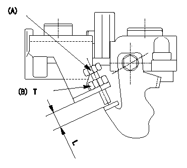
Starting injection quantity adjustment
1. Adjust the starting injection quantity so that it is as specified using the bolt (A), then fix using the nut (B) (Tightening torque T).
2. At this time, confirm that the bolt protrudes L.
----------
----------
L=7.4~11.1mm T=6~9N-m(0.6~0.9kgf-m)
----------
----------
L=7.4~11.1mm T=6~9N-m(0.6~0.9kgf-m)
0000001901 TAMPER PROOF
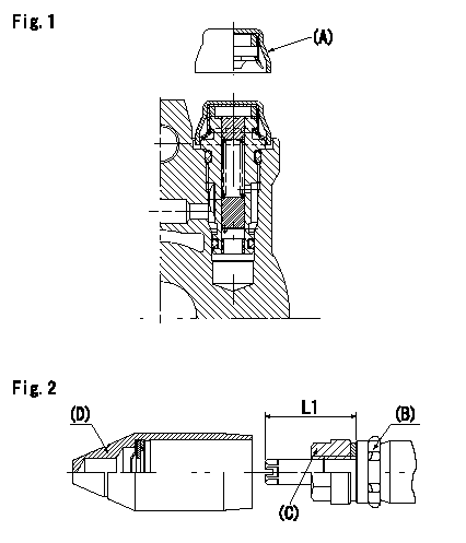
Tamperproof installation procedure
A:Cap
B:Rubber vibration damper
C:Nut
D:Cap
L1:Inspection dimension
Fig. 1 Regulating valve seal
1) Insert the cap A horizontally (press fit).
2) After insertion (press-fitting), tighten the cap to torque T1, and confirm that it is not pulled out at load F1.
Fig.2 Full load adjusting screw
1) Confirm the position of the rubber vibration damper (B) and then tighten nut (C) to the torque T2.
----------
L1=23~28mm F1=49N(5kgf) T1=4.9N-m(0.5kgf-m) T2=7~9N-m(0.7~0.9kgf-m)
----------
L1=23~28mm
----------
L1=23~28mm F1=49N(5kgf) T1=4.9N-m(0.5kgf-m) T2=7~9N-m(0.7~0.9kgf-m)
----------
L1=23~28mm
Information:
Start By:a. remove governor **See Disassemble Governor story
Keep all parts clean from contaminants. Contaminants put into the system may cause rapid wear and shortened component life.
1. Remove the bolts and the plate from the side of the fuel injection pump housing. 2. Install tool (A) in the fuel injection pump housing. Move the rack until tool (A) can be installed to hold the rack in the center position to remove the fuel injection pumps.3. Use tool (B) to remove bushing (1).4. Remove the O-ring seal from the fuel injection pump housing. 5. Install tool (C) on the bonnet and remove the fuel injection pump. 6. Remove spacer (2). Keep the spacers (2) from the fuel injection pumps together with identification as to their location in the pump housing.7. Perform steps 3 through 6 to remove the other fuel injection pumps. The following steps are to install the fuel injection pumps.8. Install spacer (2).9. Install tool (A). Move the rack until tool (A) can be installed to hold the rack in the center position. The rack must be in the center position to install the fuel injection pumps.10. Turn camshaft until the lobe of the camshaft is down for the pump to be installed.11. Install tool (C) on the bonnet on the fuel injection pump.12. Install the fuel injection pump in the pump housing with saw cut slot in the gear in alignment with the small pin and groove in the barrel in alignment with dowel in the pump housing.13. Put clean oil on O-ring seal and install it in the fuel injection pump housing.14. Install the bushing by hand until the bushing is even with the top of the housing. If the bushing can not be installed this far by hand, remove it. Remove the fuel injection pump ad put the pump in alignment again and install the bushing again.15. Install tool (B) on the bushing and tighten the bushing to a torque of 190 14 N m (140 10 lb ft).16. Install tooling (D) to measure total rack travel. Correct rack travel is 15.7 mm (.618 in). A smaller measurement is an indication of improper fuel injection pump installation.17. Perform Steps 1 through 9 to install the other fuel pumps18. Install the cover and gasket on the fuel injection pump housing.End By:a. install governor **See Assemble Governor storyDisassemble And Assemble Fuel Injection Pumps
Start By:a. remove fuel injection pumps
When the injection pumps are disassembled, handle the parts carefully. Do not damage the surfaces of the plungers, barrels and bonnets. Any scratches will cause leakage inside the fuel injection pump. The plunger and barrel for each pump are made as a set. Do not intermix the plunger of one pump in the barrel with another pump. If one part is worn, install a complete new pump assembly. Be careful when placing the plunger into the bore of the barrel.
1. Pull plunger (1) and washer (5) out of barrel (3) and spring (2).
Do not remove the gear from
Have questions with 104746-5051?
Group cross 104746-5051 ZEXEL
Isuzu
104746-5051
9 460 614 072
8972530221
INJECTION-PUMP ASSEMBLY
4JG2
4JG2