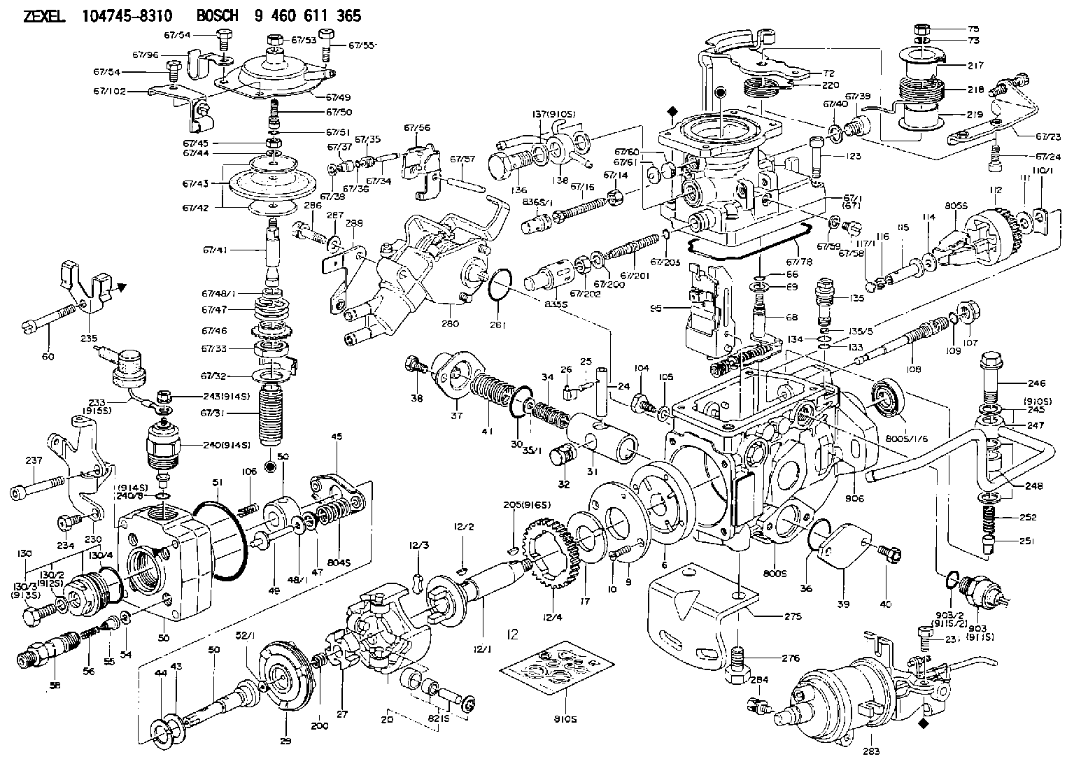
Information injection-pump assembly
BOSCH
9 460 611 365
9460611365
ZEXEL
104745-8310
1047458310

Rating:
Components :
| 0. | INJECTION-PUMP ASSEMBLY | 104745-8310 |
| 1. | _ | |
| 2. | FUEL INJECTION PUMP | 104645-8310 |
| 3. | NUMBER PLATE | 146970-5600 |
| 4. | _ | 479771-0520 |
| 5. | CAPSULE | |
| 6. | ADJUSTING DEVICE | |
| 7. | NOZZLE AND HOLDER ASSY | 105148-1311 |
| 8. | Nozzle and Holder | MD196607 |
| 9. | Open Pre:MPa(Kqf/cm2) | 14.7{150} |
| 10. | NOZZLE-HOLDER | 105078-0181 |
| 11. | NOZZLE | 105007-1300 |
Scheme ###:
| 1/6. | [1] | 146601-0700 | PACKING RING |
| 6. | [1] | 146100-0220 | SUPPLY PUMP |
| 9. | [1] | 146103-0100 | COVER |
| 10. | [2] | 139104-0000 | FLAT-HEAD SCREW |
| 12. | [1] | 146200-0320 | DRIVE SHAFT |
| 12/1. | [1] | 146200-0300 | DRIVE SHAFT |
| 12/2. | [1] | 146201-0000 | WOODRUFF KEY |
| 12/3. | [2] | 146202-0100 | DAMPER |
| 12/4. | [1] | 146203-0000 | TOOTHED GEAR |
| 17. | [1] | 146204-0000 | PLAIN WASHER |
| 20. | [1] | 146210-3520 | ROLLER SET |
| 24. | [1] | 146303-0100 | BEARING PIN |
| 25. | [1] | 146304-0000 | BEARING PIN |
| 26. | [1] | 146305-0000 | CLAMPING BAND |
| 27. | [1] | 146205-0000 | SLOTTED WASHER |
| 29. | [1] | 146220-2120 | CAM PLATE |
| 30. | [1] | 146600-0800 | O-RING |
| 31. | [1] | 146311-6320 | PUMP PLUNGER |
| 32. | [1] | 146301-0000 | SLIDING PIECE |
| 34. | [1] | 146312-2900 | COMPRESSION SPRING |
| 34B. | [1] | 146312-2800 | COMPRESSION SPRING |
| 34C. | [1] | 146312-3200 | COMPRESSION SPRING |
| 35/1. | [1] | 146690-3200 | SHIM D11.5&9.4T0.1 |
| 35/1. | [1] | 146690-3300 | SHIM D11.5&9.4T0.2 |
| 35/1. | [1] | 146690-3400 | SHIM D11.5&9.4T0.25 |
| 35/1. | [1] | 146690-3500 | SHIM D11.5&9.4T1.0 |
| 35/1. | [1] | 146690-4100 | SHIM D11.5&9.4T2 |
| 35/1. | [1] | 146690-4200 | SHIM D11.5&9.4T0.5 |
| 35/1. | [1] | 146690-4300 | SHIM D11.5&9.4T0.75 |
| 36. | [1] | 146600-0800 | O-RING |
| 37. | [1] | 146310-4020 | COVER |
| 38. | [2] | 146620-5000 | BLEEDER SCREW |
| 39. | [1] | 146310-0100 | COVER |
| 40. | [2] | 146620-5000 | BLEEDER SCREW |
| 41. | [1] | 146312-1900 | COMPRESSION SPRING |
| 43. | [1] | 146230-0000 | SHIM |
| 44. | [1] | 146230-0100 | PLAIN WASHER |
| 45. | [1] | 146231-0001 | SLOTTED WASHER |
| 47. | [2] | 146233-0000 | SLOTTED WASHER |
| 48/1. | [1] | 146603-0000 | SHIM D17.0&5.2T0.50 |
| 48/1. | [1] | 146603-0100 | SHIM D17.0&5.2T0.80 |
| 48/1. | [1] | 146603-0200 | SHIM D17.0&5.2T1.00 |
| 48/1. | [1] | 146603-0300 | SHIM D17.0&5.2T1.20 |
| 48/1. | [1] | 146603-0400 | SHIM D17.0&5.2T1.50 |
| 48/1. | [1] | 146603-0500 | SHIM D17.0&5.2T1.80 |
| 48/1. | [1] | 146603-0600 | SHIM D17.0&5.2T2.00 |
| 48/1. | [1] | 146690-1400 | SHIM D17&5.2T0.9 |
| 48/1. | [1] | 146690-1500 | SHIM D17&5.2T1.1 |
| 48/1. | [1] | 146690-1600 | SHIM D17&5.2T1.3 |
| 48/1. | [1] | 146690-1700 | SHIM D17&5.2T1.4 |
| 48/1. | [1] | 146690-1800 | SHIM D17&5.2T1.6 |
| 48/1. | [1] | 146690-1900 | SHIM D17&5.2T1.7 |
| 48/1. | [1] | 146690-5800 | SHIM |
| 48/1. | [1] | 146690-5900 | SHIM |
| 48/1. | [1] | 146690-6000 | SHIM |
| 48/1. | [1] | 146690-6100 | SHIM |
| 48/1. | [1] | 146690-6200 | SHIM |
| 48/1. | [1] | 146690-6300 | SHIM |
| 48/1. | [1] | 146690-6400 | SHIM |
| 48/1. | [1] | 146690-6500 | SHIM |
| 48/1. | [1] | 146690-6600 | SHIM |
| 48/1. | [1] | 146690-6700 | SHIM |
| 48/1. | [1] | 146690-6800 | SHIM |
| 48/1. | [1] | 146690-6900 | SHIM |
| 48/1. | [1] | 146690-7000 | SHIM |
| 48/1. | [1] | 146690-7100 | SHIM |
| 48/1. | [1] | 146690-7200 | SHIM |
| 48/1. | [1] | 146690-7300 | SHIM |
| 48/1. | [1] | 146690-7400 | SHIM |
| 48/1. | [1] | 146690-7500 | SHIM |
| 48/1. | [1] | 146690-7800 | SHIM |
| 49. | [2] | 146234-0020 | GUIDE PIN |
| 50. | [1] | 146401-3320 | HYDRAULIC HEAD |
| 50. | [1] | 146401-3320 | HYDRAULIC HEAD |
| 50. | [1] | 146401-3320 | HYDRAULIC HEAD |
| 51. | [1] | 146600-0000 | O-RING |
| 52/1. | [1] | 146420-0000 | SHIM D9.5&3.0T1.90 |
| 52/1. | [1] | 146420-0100 | SHIM D9.5&3.0T1.92 |
| 52/1. | [1] | 146420-0200 | SHIM D9.5&3.0T1.94 |
| 52/1. | [1] | 146420-0300 | SHIM D9.5&3.0T1.96 |
| 52/1. | [1] | 146420-0400 | SHIM D9.5&3.0T1.98 |
| 52/1. | [1] | 146420-0500 | SHIM D9.5&3.0T2.00 |
| 52/1. | [1] | 146420-0600 | SHIM D9.5&3.0T2.02 |
| 52/1. | [1] | 146420-0700 | SHIM D9.5&3.0T2.04 |
| 52/1. | [1] | 146420-0800 | SHIM D9.5&3.0T2.06 |
| 52/1. | [1] | 146420-0900 | SHIM D9.5&3.0T2.08 |
| 52/1. | [1] | 146420-1000 | SHIM D9.5&3.0T2.10 |
| 52/1. | [1] | 146420-1100 | SHIM D9.5&3.0T2.12 |
| 52/1. | [1] | 146420-1200 | SHIM D9.5&3.0T2.14 |
| 52/1. | [1] | 146420-1300 | SHIM D9.5&3.0T2.16 |
| 52/1. | [1] | 146420-1400 | SHIM D9.5&3.0T2.18 |
| 52/1. | [1] | 146420-1500 | SHIM D9.5&3.0T2.20 |
| 52/1. | [1] | 146420-1600 | SHIM D9.5&3.0T2.22 |
| 52/1. | [1] | 146420-1700 | SHIM D9.5&3.0T2.24 |
| 52/1. | [1] | 146420-1800 | SHIM D9.5&3.0T2.26 |
| 52/1. | [1] | 146420-1900 | SHIM D9.5&3.0T2.28 |
| 52/1. | [1] | 146420-2000 | SHIM D9.5&3.0T2.30 |
| 52/1. | [1] | 146420-2100 | SHIM D9.5&3.0T2.32 |
| 52/1. | [1] | 146420-2200 | SHIM D9.5&3.0T2.34 |
| 52/1. | [1] | 146420-2300 | SHIM D9.5&3.0T2.36 |
| 52/1. | [1] | 146420-2400 | SHIM D9.5&3.0T2.38 |
| 52/1. | [1] | 146420-2500 | SHIM D9.5&3.0T2.40 |
| 52/1. | [1] | 146420-2600 | SHIM D9.5&3.0T2.42 |
| 52/1. | [1] | 146420-2700 | SHIM D9.5&3.0T2.44 |
| 52/1. | [1] | 146420-2800 | SHIM D9.5&3.0T2.46 |
| 52/1. | [1] | 146420-2900 | SHIM D9.5&3.0T2.48 |
| 52/1. | [1] | 146420-3000 | SHIM D9.5&3.0T2.50 |
| 52/1. | [1] | 146420-3100 | SHIM D9.5&3.0T2.52 |
| 52/1. | [1] | 146420-3200 | SHIM D9.5&3.0T2.54 |
| 52/1. | [1] | 146420-3300 | SHIM D9.5&3.0T2.56 |
| 52/1. | [1] | 146420-3400 | SHIM D9.5&3.0T2.58 |
| 52/1. | [1] | 146420-3500 | SHIM D9.5&3.0T2.60 |
| 52/1. | [1] | 146420-3600 | SHIM D9.5&3.0T2.62 |
| 52/1. | [1] | 146420-3700 | SHIM D9.5&3.0T2.64 |
| 52/1. | [1] | 146420-3800 | SHIM D9.5&3.0T2.66 |
| 52/1. | [1] | 146420-3900 | SHIM D9.5&3.0T2.68 |
| 52/1. | [1] | 146420-4000 | SHIM D9.5&3.0T2.70 |
| 52/1. | [1] | 146420-4100 | SHIM D9.5&3.0T2.72 |
| 52/1. | [1] | 146420-4200 | SHIM D9.5&3.0T2.74 |
| 52/1. | [1] | 146420-4300 | SHIM D9.5&3.0T2.76 |
| 52/1. | [1] | 146420-4400 | SHIM D9.5&3.0T2.78 |
| 52/1. | [1] | 146420-4500 | SHIM D9.5&3.0T2.80 |
| 52/1. | [1] | 146420-4600 | SHIM D9.5&3.0T2.82 |
| 52/1. | [1] | 146420-4700 | SHIM D9.5&3.0T2.84 |
| 52/1. | [1] | 146420-4800 | SHIM D9.5&3.0T2.86 |
| 52/1. | [1] | 146420-4900 | SHIM D9.5&3.0T2.88 |
| 52/1. | [1] | 146420-5000 | SHIM D9.5&3.0T2.90 |
| 52/1. | [1] | 146420-5100 | SHIM D9.5&3.0T1.74 |
| 52/1. | [1] | 146420-5200 | SHIM D9.5&3.0T1.76 |
| 52/1. | [1] | 146420-5300 | SHIM D9.5&3.0T1.78 |
| 52/1. | [1] | 146420-5400 | SHIM D9.5&3.0T1.80 |
| 52/1. | [1] | 146420-5500 | SHIM D9.5&3.0T1.82 |
| 52/1. | [1] | 146420-5600 | SHIM D9.5&3.0T1.84 |
| 52/1. | [1] | 146420-5700 | SHIM D9.5&3.0T1.86 |
| 52/1. | [1] | 146420-5800 | SHIM D9.5&3.0T1.88 |
| 54. | [4] | 146433-0100 | GASKET D12&6.4T1.00 |
| 55. | [4] | 146430-2020 | DELIVERY-VALVE ASSEMBLY |
| 56. | [4] | 146432-0000 | COMPRESSION SPRING |
| 58. | [4] | 146440-0320 | FITTING |
| 60. | [3] | 139106-0100 | FLAT-HEAD SCREW |
| 67. | [1] | 146704-1120 | COMPENSATOR,MANIFOLD-PRES |
| 67/1. | [1] | 146805-7220 | GOVERNOR COVER |
| 67/2. | [1] | 146515-0320 | CONTROL SHAFT |
| 67/3. | [1] | 146600-0100 | O-RING |
| 67/4. | [1] | 139310-0200 | PLAIN WASHER |
| 67/14. | [1] | 146621-1700 | UNION NUT |
| 67/16. | [1] | 146526-3000 | BLEEDER SCREW |
| 67/23. | [1] | 146925-7520 | BRACKET |
| 67/24. | [2] | 010206-2240 | HEX-SOCKET-HEAD CAP SCREW |
| 67/31. | [1] | 146710-0700 | BUSHING |
| 67/32. | [1] | 146711-0000 | PLATE |
| 67/33. | [1] | 139218-0400 | UNION NUT |
| 67/34. | [1] | 146712-0700 | BEARING PIN |
| 67/35. | [1] | 146621-0300 | UNION NUT |
| 67/36. | [1] | 146600-1400 | O-RING |
| 67/37. | [1] | 146710-0100 | BUSHING |
| 67/38. | [1] | 139506-0200 | GASKET D8.9&6.8T1.00 |
| 67/39. | [1] | 146620-0300 | CAPSULE |
| 67/40. | [1] | 026512-1540 | GASKET D15.4&12.2T1.50 |
| 67/41. | [1] | 146713-4300 | ADJUSTING PIN |
| 67/42. | [2] | 146714-0200 | PLATE |
| 67/43. | [1] | 146715-0300 | DIAPHRAGM |
| 67/44. | [1] | 139306-0100 | LOCKING WASHER |
| 67/45. | [1] | 013030-6040 | UNION NUT M6P1H3.6 |
| 67/46. | [1] | 146716-0000 | UNION NUT |
| 67/47. | [1] | 146717-2900 | COILED SPRING |
| 67/48/1. | [1] | 146720-3000 | SPACER BUSHING L3.7 |
| 67/48/1. | [1] | 146720-3100 | SPACER BUSHING L3.9 |
| 67/48/1. | [1] | 146720-3200 | SPACER BUSHING L4.1 |
| 67/48/1. | [1] | 146720-3300 | SPACER BUSHING L4.3 |
| 67/48/1. | [1] | 146720-3400 | SPACER BUSHING L4.5 |
| 67/48/1. | [1] | 146720-3500 | SPACER BUSHING L4.7 |
| 67/48/1. | [1] | 146720-3600 | SPACER BUSHING L4.9 |
| 67/48/1. | [1] | 146720-3700 | SPACER BUSHING L5.1 |
| 67/48/1. | [1] | 146720-3800 | SPACER BUSHING L5.3 |
| 67/48/1. | [1] | 146720-3900 | SPACER BUSHING L5.5 |
| 67/48/1. | [1] | 146720-4000 | SPACER BUSHING L5.7 |
| 67/48/1. | [1] | 146720-4100 | SPACER BUSHING L5.9 |
| 67/48/1. | [1] | 146720-4200 | SPACER BUSHING L6.1 |
| 67/48/1. | [1] | 146720-4300 | SPACER BUSHING L6.3 |
| 67/48/1. | [1] | 146720-4400 | SPACER BUSHING L6.5 |
| 67/48/1. | [1] | 146720-8900 | SPACER BUSHING L6.7 |
| 67/48/1. | [1] | 146720-9000 | SPACER BUSHING L6.9 |
| 67/48/1. | [1] | 146720-9100 | SPACER BUSHING L7.1 |
| 67/48/1. | [1] | 146720-9200 | SPACER BUSHING L7.3 |
| 67/48/1. | [1] | 146720-9300 | SPACER BUSHING L7.5 |
| 67/48/1. | [1] | 146720-9400 | SPACER BUSHING L7.7 |
| 67/48/1. | [1] | 146720-9500 | SPACER BUSHING L7.9 |
| 67/48/1. | [1] | 146720-9600 | SPACER BUSHING L8.1 |
| 67/48/1. | [1] | 146720-9700 | SPACER BUSHING L8.3 |
| 67/48/1. | [1] | 146720-9800 | SPACER BUSHING L8.5 |
| 67/48/1. | [1] | 146720-9900 | SPACER BUSHING L3.6 |
| 67/48/1. | [1] | 146725-0000 | SPACER BUSHING L3.8 |
| 67/48/1. | [1] | 146725-0100 | SPACER BUSHING L4.0 |
| 67/48/1. | [1] | 146725-0200 | SPACER BUSHING L4.2 |
| 67/48/1. | [1] | 146725-0300 | SPACER BUSHING L4.4 |
| 67/48/1. | [1] | 146725-0400 | SPACER BUSHING L4.6 |
| 67/48/1. | [1] | 146725-0500 | SPACER BUSHING L4.8 |
| 67/48/1. | [1] | 146725-0600 | SPACER BUSHING L5.0 |
| 67/48/1. | [1] | 146725-0700 | SPACER BUSHING L5.2 |
| 67/48/1. | [1] | 146725-0800 | SPACER BUSHING L5.4 |
| 67/48/1. | [1] | 146725-0900 | SPACER BUSHING L5.6 |
| 67/48/1. | [1] | 146725-1000 | SPACER BUSHING L5.8 |
| 67/48/1. | [1] | 146725-1100 | SPACER BUSHING L6.0 |
| 67/48/1. | [1] | 146725-1200 | SPACER BUSHING L6.2 |
| 67/48/1. | [1] | 146725-1300 | SPACER BUSHING L6.4 |
| 67/48/1. | [1] | 146725-1400 | SPACER BUSHING L6.6 |
| 67/48/1. | [1] | 146725-1500 | SPACER BUSHING L6.8 |
| 67/48/1. | [1] | 146725-1600 | SPACER BUSHING L7.0 |
| 67/48/1. | [1] | 146725-1700 | SPACER BUSHING L7.2 |
| 67/48/1. | [1] | 146725-1800 | SPACER BUSHING L7.4 |
| 67/48/1. | [1] | 146725-1900 | SPACER BUSHING L7.6 |
| 67/48/1. | [1] | 146725-2000 | SPACER BUSHING L7.8 |
| 67/48/1. | [1] | 146725-2100 | SPACER BUSHING L8.0 |
| 67/48/1. | [1] | 146725-2200 | SPACER BUSHING L8.2 |
| 67/48/1. | [1] | 146725-2300 | SPACER BUSHING L8.4 |
| 67/48/1. | [1] | 146725-2400 | SPACER BUSHING L8.6 |
| 67/49. | [1] | 146721-3720 | COVER |
| 67/50. | [1] | 146722-0200 | FLAT-HEAD SCREW |
| 67/51. | [1] | 146600-0300 | O-RING |
| 67/53. | [1] | 013020-6040 | UNION NUT M6P1H5 |
| 67/54. | [2] | 139006-4700 | BLEEDER SCREW |
| 67/54. | [2] | 139006-4700 | BLEEDER SCREW |
| 67/55. | [2] | 139006-4600 | BLEEDER SCREW |
| 67/56. | [1] | 146723-0200 | CONTROL LEVER |
| 67/57. | [1] | 146712-0100 | BEARING PIN |
| 67/58. | [2] | 146620-0600 | CAPSULE |
| 67/59. | [2] | 026506-1040 | GASKET D9.9&6.2T1 |
| 67/60. | [1] | 146724-0300 | ELEMENT |
| 67/61. | [1] | 146724-0600 | CAPSULE |
| 67/78. | [1] | 146600-4400 | SEAL RING |
| 67/96. | [1] | 146659-7220 | CLAMPING BAND |
| 67/112. | [1] | 146926-5520 | BRACKET |
| 67/200. | [1] | 139308-0300 | PLAIN WASHER |
| 67/201. | [1] | 146545-3400 | THREADED PIN L53.00 |
| 67/201B. | [1] | 146545-3500 | THREADED PIN L55.00 |
| 67/201C. | [1] | 146545-3600 | THREADED PIN L57.00 |
| 67/202. | [1] | 139208-0900 | UNION NUT |
| 67/203. | [1] | 146600-1200 | O-RING |
| 72. | [1] | 146830-7120 | CONTROL LEVER |
| 72B. | [1] | 146830-7220 | CONTROL LEVER |
| 72C. | [1] | 146831-9120 | CONTROL LEVER |
| 72D. | [1] | 146831-9220 | CONTROL LEVER |
| 73. | [1] | 014110-6440 | LOCKING WASHER |
| 75. | [1] | 013020-6040 | UNION NUT M6P1H5 |
| 95. | [1] | 146550-1620 | FULCRUM LEVER |
| 104. | [2] | 146568-0000 | SLOTTED SPRING PIN |
| 105. | [2] | 026508-1140 | GASKET D11.4&8.2T1 |
| 106. | [2] | 146588-0500 | COILED SPRING |
| 107. | [1] | 146569-0300 | UNION NUT |
| 108. | [1] | 146570-0420 | GOVERNOR SHAFT |
| 109. | [1] | 146600-0400 | O-RING |
| 110/1. | [1] | 146571-0000 | SHIM D20.2&8.3T1.05 |
| 110/1. | [1] | 146571-0100 | SHIM D20.2&8.3T1.25 |
| 110/1. | [1] | 146571-0200 | SHIM D20.2&8.3T1.45 |
| 110/1. | [1] | 146571-0300 | SHIM D20.2&8.3T1.65 |
| 110/1. | [1] | 146571-0400 | SHIM D20.2&8.3T1.85 |
| 110/1. | [1] | 146571-0500 | SHIM D20.2&8.3T1.15 |
| 110/1. | [1] | 146571-0600 | SHIM D20.2&8.3T1.35 |
| 110/1. | [1] | 146571-0700 | SHIM D20.2&8.3T1.55 |
| 110/1. | [1] | 146571-0800 | SHIM D20.2&8.3T1.75 |
| 111. | [1] | 146602-0600 | PLAIN WASHER D20&8.4T1.40 |
| 112. | [1] | 146572-0020 | FLYWEIGHT ASSEMBLY |
| 114. | [1] | 146602-0500 | PLAIN WASHER D17&6.4T1.60 |
| 115. | [1] | 146875-8300 | SLIDING SLEEVE |
| 116. | [1] | 146576-0000 | SEALING CAP |
| 117/1. | [1] | 146577-1800 | PLUG L2.10 |
| 117/1. | [1] | 146577-1900 | PLUG L2.30 |
| 117/1. | [1] | 146577-2000 | PLUG L2.50 |
| 117/1. | [1] | 146577-2100 | PLUG L2.70 |
| 117/1. | [1] | 146577-2200 | PLUG L2.90 |
| 117/1. | [1] | 146577-2300 | PLUG L3.10 |
| 117/1. | [1] | 146577-2400 | PLUG L3.30 |
| 117/1. | [1] | 146577-2500 | PLUG L3.50 |
| 117/1. | [1] | 146577-2600 | PLUG L3.70 |
| 117/1. | [1] | 146577-2700 | PLUG L3.90 |
| 117/1. | [1] | 146577-2800 | PLUG L4.10 |
| 117/1. | [1] | 146577-2900 | PLUG L4.30 |
| 117/1. | [1] | 146577-3000 | PLUG L4.50 |
| 117/1. | [1] | 146577-3100 | PLUG L4.70 |
| 117/1. | [1] | 146577-3200 | PLUG L4.90 |
| 117/1. | [1] | 146577-3300 | PLUG L5.10 |
| 117/1. | [1] | 146577-6700 | PLUG L2.2 |
| 117/1. | [1] | 146577-6800 | PLUG L2.4 |
| 117/1. | [1] | 146577-6900 | PLUG L2.6 |
| 117/1. | [1] | 146577-7000 | PLUG L2.8 |
| 117/1. | [1] | 146577-7100 | PLUG L3.0 |
| 117/1. | [1] | 146577-7200 | PLUG L3.2 |
| 117/1. | [1] | 146577-7300 | PLUG L3.4 |
| 117/1. | [1] | 146577-7400 | PLUG L3.6 |
| 117/1. | [1] | 146577-7500 | PLUG L3.8 |
| 117/1. | [1] | 146577-7600 | PLUG L4.0 |
| 117/1. | [1] | 146577-7700 | PLUG L4.2 |
| 117/1. | [1] | 146577-7800 | PLUG L4.4 |
| 117/1. | [1] | 146577-7900 | PLUG L4.6 |
| 117/1. | [1] | 146577-8000 | PLUG L4.8 |
| 117/1. | [1] | 146577-8100 | PLUG L5.0 |
| 117/1. | [1] | 146877-0000 | PLUG L5.2 |
| 117/1. | [1] | 146877-0100 | PLUG L5.3 |
| 117/1. | [1] | 146877-0200 | PLUG L5.4 |
| 117/1. | [1] | 146877-0300 | PLUG L5.5 |
| 117/1. | [1] | 146877-4700 | PLUG |
| 117/1. | [1] | 146877-4800 | PLUG |
| 117/1. | [1] | 146877-4900 | PLUG |
| 117/1. | [1] | 146877-5000 | PLUG |
| 120. | [1] | 146879-0220 | RETAINING PIN |
| 122. | [1] | 146580-2300 | GOVERNOR SPRING |
| 123. | [4] | 146620-0500 | HEX-SOCKET-HEAD CAP SCREW |
| 130. | [1] | 146421-0020 | CAPSULE |
| 130/2. | [1] | 026508-1140 | GASKET D11.4&8.2T1 |
| 130/3. | [1] | 146422-0000 | BLEEDER SCREW |
| 130/4. | [1] | 146600-0500 | O-RING |
| 133. | [1] | 146600-0600 | O-RING |
| 134. | [1] | 146600-0700 | O-RING |
| 135. | [1] | 146110-0220 | CONTROL VALVE |
| 135/5. | [1] | 146114-0000 | SPRING WASHER |
| 136. | [1] | 146120-0020 | OVER FLOW VALVE |
| 137. | [2] | 139512-0500 | GASKET |
| 138. | [1] | 146665-4520 | INLET UNION |
| 200. | [1] | 146206-0100 | COILED SPRING |
| 205. | [1] | 029470-4030 | WOODRUFF KEY |
| 217. | [1] | 146542-5300 | SLOTTED WASHER |
| 218. | [1] | 146592-2500 | COILED SPRING |
| 219. | [1] | 146541-3000 | BUSHING |
| 220. | [1] | 146592-2600 | COILED SPRING |
| 224. | [1] | 139006-4700 | BLEEDER SCREW |
| 230. | [1] | 146931-3400 | BRACKET |
| 231. | [1] | 139006-4600 | BLEEDER SCREW |
| 233. | [1] | 146658-9020 | WIRE |
| 234. | [1] | 139006-4800 | BLEEDER SCREW |
| 235. | [1] | 146659-0600 | CLAMPING BAND |
| 237. | [1] | 146620-0200 | HEX-SOCKET-HEAD CAP SCREW |
| 240. | [1] | 146650-1220 | PULLING ELECTROMAGNET |
| 240/8. | [1] | 146600-1700 | O-RING |
| 243. | [1] | 146621-1000 | UNION NUT |
| 245. | [3] | 139512-0500 | GASKET |
| 246. | [1] | 139812-1900 | EYE BOLT |
| 247. | [1] | 146666-8520 | INLET UNION |
| 248. | [1] | 146614-0200 | SPACER BUSHING |
| 251. | [1] | 146125-0101 | FILTER |
| 252. | [1] | 146125-0200 | COILED SPRING |
| 275. | [1] | 146612-4800 | BRACKET |
| 276. | [2] | 010010-1640 | BLEEDER SCREW M10P1.5L16 4T |
| 280. | [1] | 146361-4120 | START ADVANCE ASSY |
| 281. | [1] | 146600-0800 | O-RING |
| 283. | [1] | 146679-2821 | ADJUSTING DEVICE |
| 284. | [2] | 139005-0400 | BLEEDER SCREW |
| 286. | [1] | 020106-3540 | BLEEDER SCREW |
| 287. | [1] | 014010-6140 | PLAIN WASHER D13&6.5T1 |
| 288. | [1] | 146931-6300 | BRACKET |
| 800S. | [1] | 146018-4820 | PUMP HOUSING |
| 800S/1/6. | [1] | 146601-0700 | PACKING RING |
| 804S. | [1] | 146232-0320 | COMPRESSION SPRING |
| 805S. | [1] | 146574-0120 | PARTS SET |
| 810S. | [1] | 146600-1120 | REPAIR SET |
| 821S. | [1] | 146210-5720 | ROLLER SET |
| 835S. | [1] | 146598-1000 | CAP |
| 836S/1. | [1] | 146598-0600 | CAP L18 |
| 836S/1. | [1] | 146598-0700 | CAP L21 |
| 836S/1. | [1] | 146598-0800 | CAP L24 |
| 836S/1. | [1] | 146598-0900 | CAP L27 |
| 903. | [1] | 146672-2820 | PULSE GENERATOR |
| 903/2. | [1] | 146600-1300 | O-RING &13W1.9 |
| 906. | [1] | 146970-5600 | NAMEPLATE |
| 910S. | [1] | 146600-4220 | PARTS SET |
| 910S. | [1] | 146600-4220 | PARTS SET |
| 911S. | [1] | 146672-2820 | PULSE GENERATOR |
| 911S/2. | [1] | 146600-1300 | O-RING &13W1.9 |
| 912S. | [1] | 026508-1140 | GASKET D11.4&8.2T1 |
| 913S. | [1] | 146422-0000 | BLEEDER SCREW |
| 914S. | [1] | 146699-0020 | VALVE SET |
| 914S. | [1] | 146699-0020 | VALVE SET |
| 914S. | [1] | 146699-0020 | VALVE SET |
| 915S. | [1] | 146658-9020 | WIRE |
| 916S. | [1] | 025804-1610 | WOODRUFF KEY |
Include in #2:
104745-8310
as INJECTION-PUMP ASSEMBLY
Cross reference number
BOSCH
9 460 611 365
9460611365
ZEXEL
104745-8310
1047458310
Zexel num
Bosch num
Firm num
Name
Calibration Data:
Adjustment conditions
Test oil
1404 Test oil ISO4113orSAEJ967d
1404 Test oil ISO4113orSAEJ967d
Test oil temperature
degC
45
45
50
Nozzle
105780-0060
Bosch type code
NP-DN0SD1510
Nozzle holder
105780-2150
Opening pressure
MPa
13
13
13.3
Opening pressure
kgf/cm2
133
133
136
Injection pipe
157805-7320
Injection pipe
Outer diameter - inner diameter - length (mm) mm 2-6-450
Outer diameter - inner diameter - length (mm) mm 2-6-450
Joint assembly
157641-4720
Tube assembly
157641-4020
Transfer pump pressure
kPa
20
20
20
Transfer pump pressure
kgf/cm2
0.2
0.2
0.2
Direction of rotation (viewed from drive side)
Right R
Right R
Injection timing adjustment
Pump speed
r/min
750
750
750
Boost pressure
kPa
0
0
0
Boost pressure
mmHg
0
0
0
Average injection quantity
mm3/st.
52.6
52.1
53.1
Difference in delivery
mm3/st.
4
Basic
*
Oil temperature
degC
50
48
52
Remarks
NA
NA
Injection timing adjustment_02
Pump speed
r/min
750
750
750
Boost pressure
kPa
44
42.7
45.3
Boost pressure
mmHg
330
320
340
Average injection quantity
mm3/st.
62.6
62.1
63.1
Difference in delivery
mm3/st.
5
Basic
*
Oil temperature
degC
50
48
52
Remarks
CBS
CBS
Injection timing adjustment_03
Pump speed
r/min
1250
1250
1250
Boost pressure
kPa
73.3
72
74.6
Boost pressure
mmHg
550
540
560
Average injection quantity
mm3/st.
76.6
76.1
77.1
Difference in delivery
mm3/st.
6
Basic
*
Oil temperature
degC
50
48
52
Remarks
Full
Full
Injection timing adjustment_04
Pump speed
r/min
750
750
750
Boost pressure
kPa
0
0
0
Boost pressure
mmHg
0
0
0
Average injection quantity
mm3/st.
52.6
51.6
53.6
Difference in delivery
mm3/st.
4.5
Basic
*
Oil temperature
degC
50
48
52
Remarks
NA
NA
Injection timing adjustment_05
Pump speed
r/min
750
750
750
Boost pressure
kPa
44
42.7
45.3
Boost pressure
mmHg
330
320
340
Average injection quantity
mm3/st.
62.6
61.6
63.6
Difference in delivery
mm3/st.
5.5
Basic
*
Oil temperature
degC
50
48
52
Remarks
CBS
CBS
Injection timing adjustment_06
Pump speed
r/min
1000
1000
1000
Boost pressure
kPa
73.3
72
74.6
Boost pressure
mmHg
550
540
560
Average injection quantity
mm3/st.
77
74.5
79.5
Oil temperature
degC
50
48
52
Injection timing adjustment_07
Pump speed
r/min
1250
1250
1250
Boost pressure
kPa
73.3
72
74.6
Boost pressure
mmHg
550
540
560
Average injection quantity
mm3/st.
76.6
75.6
77.6
Difference in delivery
mm3/st.
6.5
Basic
*
Oil temperature
degC
50
48
52
Remarks
Full
Full
Injection timing adjustment_08
Pump speed
r/min
2100
2100
2100
Boost pressure
kPa
73.3
72
74.6
Boost pressure
mmHg
550
540
560
Average injection quantity
mm3/st.
65
62.5
67.5
Oil temperature
degC
52
50
54
Injection quantity adjustment
Pump speed
r/min
2650
2650
2650
Boost pressure
kPa
73.3
72
74.6
Boost pressure
mmHg
550
540
560
Average injection quantity
mm3/st.
27.9
24.9
30.9
Difference in delivery
mm3/st.
8.5
Basic
*
Oil temperature
degC
55
52
58
Injection quantity adjustment_02
Pump speed
r/min
2650
2650
2650
Boost pressure
kPa
73.3
72
74.6
Boost pressure
mmHg
550
540
560
Average injection quantity
mm3/st.
27.9
22.9
32.9
Difference in delivery
mm3/st.
9
Basic
*
Oil temperature
degC
55
52
58
Injection quantity adjustment_03
Pump speed
r/min
2950
2950
2950
Boost pressure
kPa
73.3
72
74.6
Boost pressure
mmHg
550
540
560
Average injection quantity
mm3/st.
5
Oil temperature
degC
55
52
58
Governor adjustment
Pump speed
r/min
375
375
375
Boost pressure
kPa
0
0
0
Boost pressure
mmHg
0
0
0
Average injection quantity
mm3/st.
19.4
17.9
20.9
Difference in delivery
mm3/st.
2
Basic
*
Oil temperature
degC
48
46
50
Governor adjustment_02
Pump speed
r/min
375
375
375
Boost pressure
kPa
0
0
0
Boost pressure
mmHg
0
0
0
Average injection quantity
mm3/st.
19.4
17.4
21.4
Difference in delivery
mm3/st.
2.5
Basic
*
Oil temperature
degC
48
46
50
Governor adjustment_03
Pump speed
r/min
750
750
750
Boost pressure
kPa
0
0
0
Boost pressure
mmHg
0
0
0
Average injection quantity
mm3/st.
8
Oil temperature
degC
50
48
52
Timer adjustment
Pump speed
r/min
100
100
100
Boost pressure
kPa
0
0
0
Boost pressure
mmHg
0
0
0
Average injection quantity
mm3/st.
75
65
85
Basic
*
Oil temperature
degC
48
46
50
Remarks
IDLE
IDLE
Timer adjustment_02
Pump speed
r/min
100
100
100
Boost pressure
kPa
0
0
0
Boost pressure
mmHg
0
0
0
Average injection quantity
mm3/st.
75
65
85
Oil temperature
degC
48
46
50
Remarks
IDLE
IDLE
Speed control lever angle
Pump speed
r/min
375
375
375
Boost pressure
kPa
0
0
0
Boost pressure
mmHg
0
0
0
Average injection quantity
mm3/st.
0
0
0
Oil temperature
degC
48
46
50
Remarks
Magnet OFF at idling position
Magnet OFF at idling position
0000000901
Pump speed
r/min
1250
1250
1250
Boost pressure
kPa
73.3
72
74.6
Boost pressure
mmHg
550
540
560
Overflow quantity
cm3/min
420
290
550
Oil temperature
degC
50
48
52
Stop lever angle
Pump speed
r/min
1250
1250
1250
Boost pressure
kPa
73.3
72
74.6
Boost pressure
mmHg
550
540
560
Pressure
kPa
549
520
578
Pressure
kgf/cm2
5.6
5.3
5.9
Basic
*
Oil temperature
degC
50
48
52
Stop lever angle_02
Pump speed
r/min
500
500
500
Boost pressure
kPa
73.3
72
74.6
Boost pressure
mmHg
550
540
560
Pressure
kPa
373
334
412
Pressure
kgf/cm2
3.8
3.4
4.2
Oil temperature
degC
48
46
50
Stop lever angle_03
Pump speed
r/min
1250
1250
1250
Boost pressure
kPa
73.3
72
74.6
Boost pressure
mmHg
550
540
560
Pressure
kPa
549
510
588
Pressure
kgf/cm2
5.6
5.2
6
Basic
*
Oil temperature
degC
50
48
52
Stop lever angle_04
Pump speed
r/min
2100
2100
2100
Boost pressure
kPa
73.3
72
74.6
Boost pressure
mmHg
550
540
560
Pressure
kPa
736
697
775
Pressure
kgf/cm2
7.5
7.1
7.9
Oil temperature
degC
52
50
54
0000001101
Pump speed
r/min
1250
1250
1250
Boost pressure
kPa
73.3
72
74.6
Boost pressure
mmHg
550
540
560
Timer stroke
mm
4.6
4.4
4.8
Basic
*
Oil temperature
degC
50
48
52
_02
Pump speed
r/min
500
500
500
Boost pressure
kPa
73.3
72
74.6
Boost pressure
mmHg
550
540
560
Timer stroke
mm
1.2
0.6
1.8
Oil temperature
degC
48
46
50
_03
Pump speed
r/min
1000
1000
1000
Boost pressure
kPa
73.3
72
74.6
Boost pressure
mmHg
550
540
560
Timer stroke
mm
3.5
2.9
4.1
Oil temperature
degC
50
48
52
_04
Pump speed
r/min
1250
1250
1250
Boost pressure
kPa
73.3
72
74.6
Boost pressure
mmHg
550
540
560
Timer stroke
mm
4.6
4.2
5
Basic
*
Oil temperature
degC
50
48
52
_05
Pump speed
r/min
1500
1500
1500
Boost pressure
kPa
73.3
72
74.6
Boost pressure
mmHg
550
540
560
Timer stroke
mm
5.6
5
6.2
Oil temperature
degC
50
48
52
_06
Pump speed
r/min
2100
2100
2100
Boost pressure
kPa
73.3
72
74.6
Boost pressure
mmHg
550
540
560
Timer stroke
mm
7.8
7.2
8.4
Oil temperature
degC
52
50
54
0000001201
Max. applied voltage
V
8
8
8
Test voltage
V
13
12
14
0000001401
Pump speed
r/min
1250
1250
1250
Boost pressure
kPa
73.3
72
74.6
Boost pressure
mmHg
550
540
560
Average injection quantity
mm3/st.
56.9
56.4
57.4
Timer stroke TA
mm
3.9
3.7
4.1
Timer stroke variation dT
mm
0.7
0.7
0.7
Basic
*
Oil temperature
degC
50
48
52
_02
Pump speed
r/min
1250
1250
1250
Boost pressure
kPa
73.3
72
74.6
Boost pressure
mmHg
550
540
560
Average injection quantity
mm3/st.
56.9
55.9
57.9
Timer stroke TA
mm
3.9
3.5
4.3
Timer stroke variation dT
mm
0.7
0.7
0.7
Basic
*
Oil temperature
degC
50
48
52
_03
Pump speed
r/min
1250
1250
1250
Boost pressure
kPa
73.3
72
74.6
Boost pressure
mmHg
550
540
560
Average injection quantity
mm3/st.
43
42
44
Timer stroke TA
mm
2.5
1.9
3.1
Timer stroke variation dT
mm
2.1
2.1
2.1
Oil temperature
degC
50
48
52
Timing setting
K dimension
mm
3.3
3.2
3.4
KF dimension
mm
5.8
5.7
5.9
MS dimension
mm
1.2
1.1
1.3
BCS stroke
mm
5.7
5.5
5.9
Control lever angle alpha
deg.
59
55
63
Control lever angle beta
deg.
42
37
47
Test data Ex:
0000001801 W-CSD ADJUSTMENT
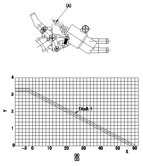
Adjustment of the W-CSD
Adjustment of the timer advance angle
Adjust screw (A) so that the timer stroke is the value determined from the graph (B).
(C) graph TA = -0.0526t+3.14 (-3<=t(deg C))
X:Temperature t (deg C)
Y:Timer stroke TA (mm)
----------
----------
----------
----------
0000001901 W-FICD LEVER ADJUSTMENT
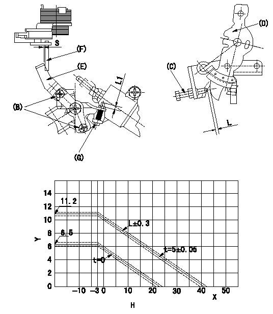
W-FICD adjustment
(1)Insert a block gauge L+-0.05 (mm) determined from the graph H between the control lever (D) and the idling stopper bolt (C).
(2)Insert a shim S+-0.5 (mm) between the W-FICD lever (E) and the control lever (F). Adjust the W-FICD lever (E) so that it contacts the control lever (F) and fix it using bolt (B). (Tighten to torque T.)
(3)The temperature of the wax at adjustment must not exceed a.
(4)After completing adjustment, confirm that screw (G) has an adjusting margin of at least L1.
Y:Control lever L (mm)
X:Temperature t (deg C)
H:Block gauge thickness L diagram
----------
S=5mm L=-0.256t+10.39(-3<=t)(S=5+-0.05) L1=3mm T=3.4~4.9N-m(0.35~0.5kgf-m) a=30degC
----------
S=5mm L1=3mm H=L=-0.256t+10.39(-3<=t)(S=5+-0.05)
----------
S=5mm L=-0.256t+10.39(-3<=t)(S=5+-0.05) L1=3mm T=3.4~4.9N-m(0.35~0.5kgf-m) a=30degC
----------
S=5mm L1=3mm H=L=-0.256t+10.39(-3<=t)(S=5+-0.05)
0000002001 V-FICD ADJUSTMENT
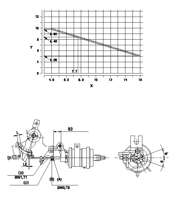
Adjustment of the two stage actuator (FICD).
X:Injection quantity Q (cm3/st)
Y:Thickness of the shim L (mm)
1. Selecting the shim for adjusting the actuator.
(1)Insert the shim L1 between the control lever and the idling stopper bolt at N; then measure the injection quantity.
(2)Select the thickness L of the shim for adjusting the actuator utilizing the following formula (refer to the graph).
Calculation: L+-0.1 = -0.4045Q+11.549(mm)(4.0<=Q<=16.0(mm3/st)
2. Adjustment of the actuator
(1)Mount the actuator to the injection pump.
(2)Position the control lever in the idling position.
(3)Adjust with the nut (D) so that the space between the control lever and the rod is L2.
(4)Insert the shim L determined above between the control lever and the idling stopper bolt.
(5)Adjust the position of screw (A) so that the actuator moves through its full stroke (reference value: approx. L3), then fix using nut (B).
(6)Rod position's allowable angle of rotation: c
----------
N=900r/min L1=8.4mm L2=1+1mm L3=(9.6mm) c=+-20deg
----------
L2=1+1mm SW1=SW7 SW2=SW8 T1=1.4~2N-m(0.14~0.2kgf-m) T2=3.5~5N-m(0.35~0.5kgf-m) a=20deg b=20deg
----------
N=900r/min L1=8.4mm L2=1+1mm L3=(9.6mm) c=+-20deg
----------
L2=1+1mm SW1=SW7 SW2=SW8 T1=1.4~2N-m(0.14~0.2kgf-m) T2=3.5~5N-m(0.35~0.5kgf-m) a=20deg b=20deg
Information:
start by:a) remove turbocharger1. Put identification marks on the two housings and the cartridge assembly for use at assembly. 2. Remove two clamps (3) and make a separation of compressor housing (1) and turbine housing (2) from the cartridge assembly.
When the nut is loosened, do not put a side force on the shaft.
3. Put cartridge assembly (4) in position on tooling (A). Remove the nut from the shaft. 4. Use a press to push the shaft assembly out of the cartridge assembly. Remove compressor wheel (5). 5. Remove seal ring (8) and shroud (7) from shaft assembly (6). 6. Remove snap ring (9) with tool (B). 7. Use two screwdrivers to remove insert (10) from the cartridge housing. 8. Remove O-ring seal (12) from the insert.9. Remove sleeve (11) from the insert. Remove the seal ring from the sleeve. 10. Remove deflector (13) from the housing. 11. Remove bearing (14) from the cartridge housing. 12. Remove sleeve (15) and bearing (16) from the cartridge housing. 13. Remove ring (17). 14. Use tool (C) to remove snap ring (19), bearing (18) and snap ring (20) from the cartridge housing. 15. Turn the cartridge housing over. Use tool (C) to remove snap ring (22), bearing (21) and snap ring (23) from the housing.Assemble Turbocharger (Schwitzer 4MF)
1. Make sure all oil passages are open and clean. Put clean engine oil on all parts before assembly. 2. Use tool (A) to install snap ring (2), bearing (3) and snap ring (1) in the housing. Install the snap rings with the round side toward the bearing. 3. Turn the housing over. Use tool (A) to install snap ring (5), bearing (6) and snap ring (4). Install the snap rings with the round side toward the bearing. 4. Put ring (7) in position in the housing. 5. Put bearing (8) in position. Make an alignment of the holes in the bearing with the dowels in the housing. Grooved side of the bearing must be up.6. Put sleeve (9) in position in the housing. 7. Put ring (10) in position on top of the bearing. 8. Install deflector (11) as shown. 9. Put seal ring (13) in position on sleeve (12). Install the sleeve in insert (15).10. Put O-ring seal (14) in position on the insert. 11. Put insert assembly (16) in position in the housing. 12. Use tool (B) to install snap ring (17) in the housing. 13. Put shaft assembly (18) in position on tooling (C).14. Put 6V2055 High Vacuum Grease in the seal ring groove on the shaft assembly.15. Install seal ring (19) on shaft assembly (18). 16. Put shroud (20) in position on the shaft assembly.17. Put cartridge housing (22) and compressor wheel (21) in position on the shaft assembly.
Do not put a side force on the shaft when the nut is tightened.
18. Put a small amount of oil on the face of the compressor wheel that will be under the nut. Install the nut and tighten it to a torque