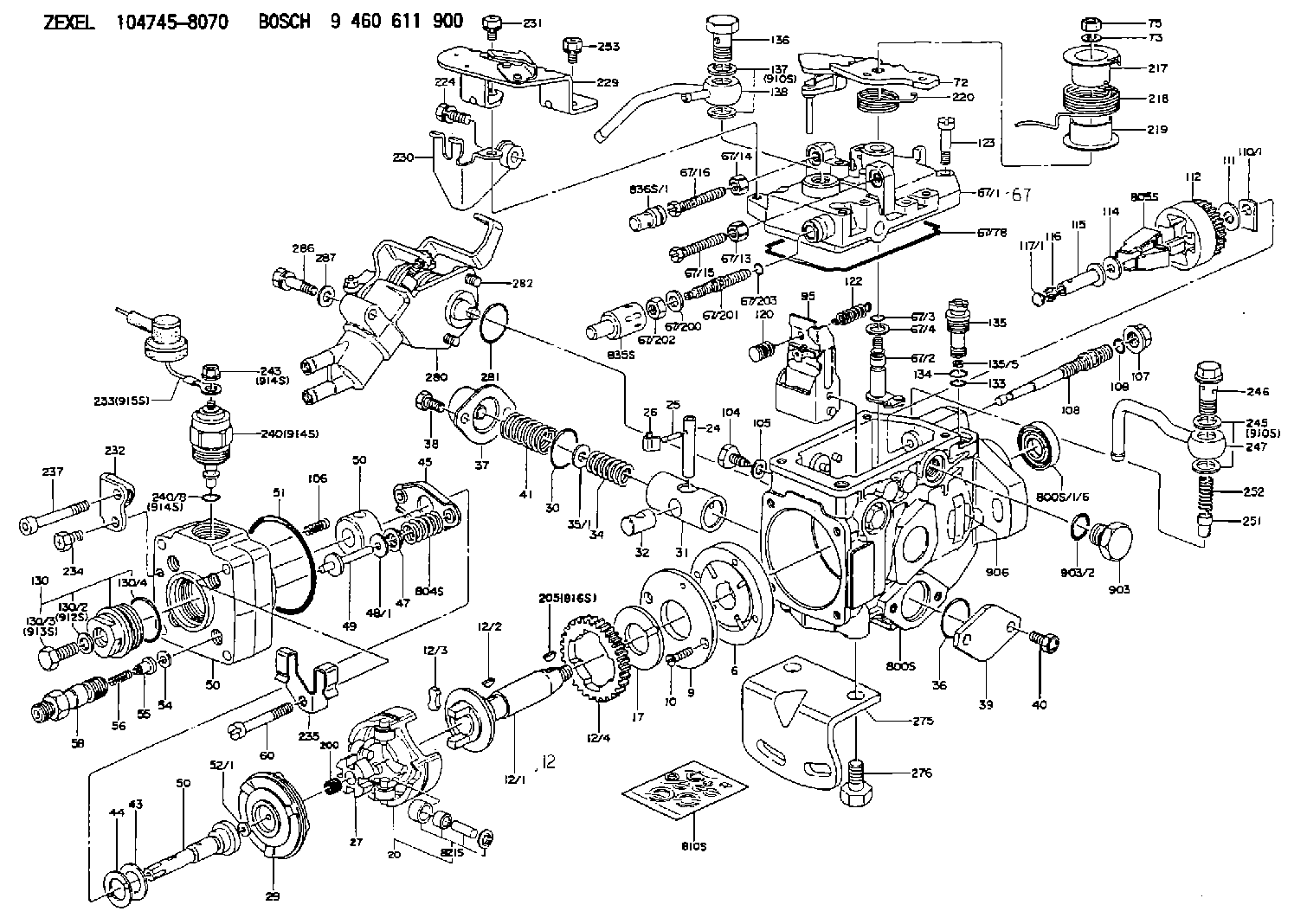
Information injection-pump assembly
BOSCH
9 460 611 900
9460611900
ZEXEL
104745-8070
1047458070
MITSUBISHI
MD331231
md331231

Rating:
Components :
| 0. | INJECTION-PUMP ASSEMBLY | 104745-8070 |
| 1. | _ | |
| 2. | FUEL INJECTION PUMP | 104645-8070 |
| 3. | NUMBER PLATE | 146959-4600 |
| 4. | _ | |
| 5. | CAPSULE | |
| 6. | ADJUSTING DEVICE | |
| 7. | NOZZLE AND HOLDER ASSY | 105148-1311 |
| 8. | Nozzle and Holder | MD196607 |
| 9. | Open Pre:MPa(Kqf/cm2) | 14.7{150} |
| 10. | NOZZLE-HOLDER | 105078-0181 |
| 11. | NOZZLE | 105007-1300 |
Scheme ###:
| 1/6. | [1] | 146601-0700 | PACKING RING |
| 6. | [1] | 146100-0220 | SUPPLY PUMP |
| 9. | [1] | 146103-0100 | COVER |
| 10. | [2] | 139104-0000 | FLAT-HEAD SCREW |
| 12. | [1] | 146200-0320 | DRIVE SHAFT |
| 12/1. | [1] | 146200-0300 | DRIVE SHAFT |
| 12/2. | [1] | 146201-0000 | WOODRUFF KEY |
| 12/3. | [2] | 146202-0100 | DAMPER |
| 12/4. | [1] | 146203-0000 | TOOTHED GEAR |
| 17. | [1] | 146204-0000 | PLAIN WASHER |
| 20. | [1] | 146210-3520 | ROLLER SET |
| 24. | [1] | 146303-0100 | BEARING PIN |
| 25. | [1] | 146304-0000 | BEARING PIN |
| 26. | [1] | 146305-0000 | CLAMPING BAND |
| 27. | [1] | 146205-0000 | SLOTTED WASHER |
| 29. | [1] | 146220-2120 | CAM PLATE |
| 30. | [1] | 146600-0800 | O-RING |
| 31. | [1] | 146311-6520 | PUMP PLUNGER |
| 32. | [1] | 146301-0000 | SLIDING PIECE |
| 34. | [1] | 146312-2800 | COMPRESSION SPRING |
| 34B. | [1] | 146312-2900 | COMPRESSION SPRING |
| 34C. | [1] | 146312-2700 | COMPRESSION SPRING |
| 35/1. | [1] | 146690-3200 | SHIM D11.5&9.4T0.1 |
| 35/1. | [1] | 146690-3300 | SHIM D11.5&9.4T0.2 |
| 35/1. | [1] | 146690-3400 | SHIM D11.5&9.4T0.25 |
| 35/1. | [1] | 146690-3500 | SHIM D11.5&9.4T1.0 |
| 35/1. | [1] | 146690-4100 | SHIM D11.5&9.4T2 |
| 35/1. | [1] | 146690-4200 | SHIM D11.5&9.4T0.5 |
| 35/1. | [1] | 146690-4300 | SHIM D11.5&9.4T0.75 |
| 36. | [1] | 146600-0800 | O-RING |
| 37. | [1] | 146310-4020 | COVER |
| 38. | [2] | 146620-5000 | BLEEDER SCREW |
| 39. | [1] | 146310-0100 | COVER |
| 40. | [2] | 146620-5000 | BLEEDER SCREW |
| 41. | [1] | 146312-1900 | COMPRESSION SPRING |
| 43. | [1] | 146230-0000 | SHIM |
| 44. | [1] | 146230-0100 | PLAIN WASHER |
| 45. | [1] | 146231-0001 | SLOTTED WASHER |
| 47. | [2] | 146233-0000 | SLOTTED WASHER |
| 48/1. | [1] | 146603-0000 | SHIM D17.0&5.2T0.50 |
| 48/1. | [1] | 146603-0100 | SHIM D17.0&5.2T0.80 |
| 48/1. | [1] | 146603-0200 | SHIM D17.0&5.2T1.00 |
| 48/1. | [1] | 146603-0300 | SHIM D17.0&5.2T1.20 |
| 48/1. | [1] | 146603-0400 | SHIM D17.0&5.2T1.50 |
| 48/1. | [1] | 146603-0500 | SHIM D17.0&5.2T1.80 |
| 48/1. | [1] | 146603-0600 | SHIM D17.0&5.2T2.00 |
| 48/1. | [1] | 146690-1400 | SHIM D17&5.2T0.9 |
| 48/1. | [1] | 146690-1500 | SHIM D17&5.2T1.1 |
| 48/1. | [1] | 146690-1600 | SHIM D17&5.2T1.3 |
| 48/1. | [1] | 146690-1700 | SHIM D17&5.2T1.4 |
| 48/1. | [1] | 146690-1800 | SHIM D17&5.2T1.6 |
| 48/1. | [1] | 146690-1900 | SHIM D17&5.2T1.7 |
| 48/1. | [1] | 146690-5800 | SHIM D17&5.2T2.1 |
| 48/1. | [1] | 146690-5900 | SHIM D17&5.2T2.2 |
| 48/1. | [1] | 146690-6000 | SHIM D17&5.2T2.3 |
| 48/1. | [1] | 146690-6100 | SHIM D17&5.2T2.4 |
| 48/1. | [1] | 146690-6200 | SHIM D17&5.2T2.5 |
| 48/1. | [1] | 146690-6300 | SHIM D17&5.2T2.6 |
| 48/1. | [1] | 146690-6400 | SHIM D17&5.2T2.7 |
| 48/1. | [1] | 146690-6500 | SHIM D17&5.2T2.8 |
| 48/1. | [1] | 146690-6600 | SHIM D17&5.2T2.9 |
| 48/1. | [1] | 146690-6700 | SHIM D17&5.2T3.0 |
| 48/1. | [1] | 146690-6800 | SHIM D17&5.2T3.1 |
| 48/1. | [1] | 146690-6900 | SHIM D17&5.2T3.2 |
| 48/1. | [1] | 146690-7000 | SHIM D17&5.2T3.3 |
| 48/1. | [1] | 146690-7100 | SHIM D17&5.2T3.4 |
| 48/1. | [1] | 146690-7200 | SHIM D17&5.2T0.4 |
| 48/1. | [1] | 146690-7300 | SHIM D17&5.2T0.6 |
| 48/1. | [1] | 146690-7400 | SHIM D17&5.2T0.7 |
| 48/1. | [1] | 146690-7500 | SHIM D17&5.2T1.9 |
| 48/1. | [1] | 146690-7800 | SHIM D17&5.2T0.2 |
| 49. | [2] | 146234-0500 | GUIDE PIN |
| 50. | [1] | 146401-0221 | HYDRAULIC HEAD |
| 50. | [1] | 146401-0221 | HYDRAULIC HEAD |
| 50. | [1] | 146401-0221 | HYDRAULIC HEAD |
| 51. | [1] | 146600-0000 | O-RING |
| 52/1. | [1] | 146420-0000 | SHIM D9.5&3.0T1.90 |
| 52/1. | [1] | 146420-0100 | SHIM D9.5&3.0T1.92 |
| 52/1. | [1] | 146420-0200 | SHIM D9.5&3.0T1.94 |
| 52/1. | [1] | 146420-0300 | SHIM D9.5&3.0T1.96 |
| 52/1. | [1] | 146420-0400 | SHIM D9.5&3.0T1.98 |
| 52/1. | [1] | 146420-0500 | SHIM D9.5&3.0T2.00 |
| 52/1. | [1] | 146420-0600 | SHIM D9.5&3.0T2.02 |
| 52/1. | [1] | 146420-0700 | SHIM D9.5&3.0T2.04 |
| 52/1. | [1] | 146420-0800 | SHIM D9.5&3.0T2.06 |
| 52/1. | [1] | 146420-0900 | SHIM D9.5&3.0T2.08 |
| 52/1. | [1] | 146420-1000 | SHIM D9.5&3.0T2.10 |
| 52/1. | [1] | 146420-1100 | SHIM D9.5&3.0T2.12 |
| 52/1. | [1] | 146420-1200 | SHIM D9.5&3.0T2.14 |
| 52/1. | [1] | 146420-1300 | SHIM D9.5&3.0T2.16 |
| 52/1. | [1] | 146420-1400 | SHIM D9.5&3.0T2.18 |
| 52/1. | [1] | 146420-1500 | SHIM D9.5&3.0T2.20 |
| 52/1. | [1] | 146420-1600 | SHIM D9.5&3.0T2.22 |
| 52/1. | [1] | 146420-1700 | SHIM D9.5&3.0T2.24 |
| 52/1. | [1] | 146420-1800 | SHIM D9.5&3.0T2.26 |
| 52/1. | [1] | 146420-1900 | SHIM D9.5&3.0T2.28 |
| 52/1. | [1] | 146420-2000 | SHIM D9.5&3.0T2.30 |
| 52/1. | [1] | 146420-2100 | SHIM D9.5&3.0T2.32 |
| 52/1. | [1] | 146420-2200 | SHIM D9.5&3.0T2.34 |
| 52/1. | [1] | 146420-2300 | SHIM D9.5&3.0T2.36 |
| 52/1. | [1] | 146420-2400 | SHIM D9.5&3.0T2.38 |
| 52/1. | [1] | 146420-2500 | SHIM D9.5&3.0T2.40 |
| 52/1. | [1] | 146420-2600 | SHIM D9.5&3.0T2.42 |
| 52/1. | [1] | 146420-2700 | SHIM D9.5&3.0T2.44 |
| 52/1. | [1] | 146420-2800 | SHIM D9.5&3.0T2.46 |
| 52/1. | [1] | 146420-2900 | SHIM D9.5&3.0T2.48 |
| 52/1. | [1] | 146420-3000 | SHIM D9.5&3.0T2.50 |
| 52/1. | [1] | 146420-3100 | SHIM D9.5&3.0T2.52 |
| 52/1. | [1] | 146420-3200 | SHIM D9.5&3.0T2.54 |
| 52/1. | [1] | 146420-3300 | SHIM D9.5&3.0T2.56 |
| 52/1. | [1] | 146420-3400 | SHIM D9.5&3.0T2.58 |
| 52/1. | [1] | 146420-3500 | SHIM D9.5&3.0T2.60 |
| 52/1. | [1] | 146420-3600 | SHIM D9.5&3.0T2.62 |
| 52/1. | [1] | 146420-3700 | SHIM D9.5&3.0T2.64 |
| 52/1. | [1] | 146420-3800 | SHIM D9.5&3.0T2.66 |
| 52/1. | [1] | 146420-3900 | SHIM D9.5&3.0T2.68 |
| 52/1. | [1] | 146420-4000 | SHIM D9.5&3.0T2.70 |
| 52/1. | [1] | 146420-4100 | SHIM D9.5&3.0T2.72 |
| 52/1. | [1] | 146420-4200 | SHIM D9.5&3.0T2.74 |
| 52/1. | [1] | 146420-4300 | SHIM D9.5&3.0T2.76 |
| 52/1. | [1] | 146420-4400 | SHIM D9.5&3.0T2.78 |
| 52/1. | [1] | 146420-4500 | SHIM D9.5&3.0T2.80 |
| 52/1. | [1] | 146420-4600 | SHIM D9.5&3.0T2.82 |
| 52/1. | [1] | 146420-4700 | SHIM D9.5&3.0T2.84 |
| 52/1. | [1] | 146420-4800 | SHIM D9.5&3.0T2.86 |
| 52/1. | [1] | 146420-4900 | SHIM D9.5&3.0T2.88 |
| 52/1. | [1] | 146420-5000 | SHIM D9.5&3.0T2.90 |
| 52/1. | [1] | 146420-5100 | SHIM D9.5&3.0T1.74 |
| 52/1. | [1] | 146420-5200 | SHIM D9.5&3.0T1.76 |
| 52/1. | [1] | 146420-5300 | SHIM D9.5&3.0T1.78 |
| 52/1. | [1] | 146420-5400 | SHIM D9.5&3.0T1.80 |
| 52/1. | [1] | 146420-5500 | SHIM D9.5&3.0T1.82 |
| 52/1. | [1] | 146420-5600 | SHIM D9.5&3.0T1.84 |
| 52/1. | [1] | 146420-5700 | SHIM D9.5&3.0T1.86 |
| 52/1. | [1] | 146420-5800 | SHIM D9.5&3.0T1.88 |
| 54. | [4] | 146433-0100 | GASKET D12&6.4T1.00 |
| 55. | [4] | 146430-0320 | DELIVERY-VALVE ASSEMBLY |
| 56. | [4] | 146432-0000 | COMPRESSION SPRING |
| 58. | [4] | 146440-0320 | FITTING |
| 60. | [3] | 139106-0100 | FLAT-HEAD SCREW |
| 67. | [1] | 146820-2320 | GOVERNOR COVER |
| 67/1. | [1] | 146508-8221 | GOVERNOR COVER |
| 67/2. | [1] | 146515-0320 | CONTROL SHAFT |
| 67/3. | [1] | 146600-0100 | O-RING |
| 67/4. | [1] | 139310-0200 | PLAIN WASHER |
| 67/13. | [1] | 146621-1700 | UNION NUT |
| 67/14. | [1] | 146621-1700 | UNION NUT |
| 67/15. | [1] | 146526-3400 | BLEEDER SCREW |
| 67/16. | [1] | 146526-2800 | BLEEDER SCREW |
| 67/78. | [1] | 146600-4400 | SEAL RING |
| 67/200. | [1] | 139308-0300 | PLAIN WASHER |
| 67/201. | [1] | 146545-3400 | THREADED PIN L53.00 |
| 67/201B. | [1] | 146545-3500 | THREADED PIN L55.00 |
| 67/201C. | [1] | 146545-3600 | THREADED PIN L57.00 |
| 67/202. | [1] | 139208-0900 | UNION NUT |
| 67/203. | [1] | 146600-1200 | O-RING |
| 72. | [1] | 146830-7620 | CONTROL LEVER |
| 72B. | [1] | 146830-7720 | CONTROL LEVER |
| 73. | [1] | 014110-6440 | LOCKING WASHER |
| 75. | [1] | 013020-6040 | UNION NUT M6P1H5 |
| 95. | [1] | 146551-6120 | FULCRUM LEVER |
| 104. | [2] | 146568-0000 | SLOTTED SPRING PIN |
| 105. | [2] | 026508-1140 | GASKET D11.4&8.2T1 |
| 106. | [2] | 146588-0500 | COILED SPRING |
| 107. | [1] | 146569-0300 | UNION NUT |
| 108. | [1] | 146570-0420 | GOVERNOR SHAFT |
| 109. | [1] | 146600-0400 | O-RING |
| 110/1. | [1] | 146571-0000 | SHIM D20.2&8.3T1.05 |
| 110/1. | [1] | 146571-0100 | SHIM D20.2&8.3T1.25 |
| 110/1. | [1] | 146571-0200 | SHIM D20.2&8.3T1.45 |
| 110/1. | [1] | 146571-0300 | SHIM D20.2&8.3T1.65 |
| 110/1. | [1] | 146571-0400 | SHIM D20.2&8.3T1.85 |
| 110/1. | [1] | 146571-0500 | SHIM D20.2&8.3T1.15 |
| 110/1. | [1] | 146571-0600 | SHIM D20.2&8.3T1.35 |
| 110/1. | [1] | 146571-0700 | SHIM D20.2&8.3T1.55 |
| 110/1. | [1] | 146571-0800 | SHIM D20.2&8.3T1.75 |
| 111. | [1] | 146602-0600 | PLAIN WASHER D20&8.4T1.40 |
| 112. | [1] | 146572-0020 | FLYWEIGHT ASSEMBLY |
| 114. | [1] | 146602-0500 | PLAIN WASHER D17&6.4T1.60 |
| 115. | [1] | 146975-7900 | SLIDING SLEEVE |
| 116. | [1] | 146576-0000 | SEALING CAP |
| 117/1. | [1] | 146577-1800 | PLUG L2.10 |
| 117/1. | [1] | 146577-1900 | PLUG L2.30 |
| 117/1. | [1] | 146577-2000 | PLUG L2.50 |
| 117/1. | [1] | 146577-2100 | PLUG L2.70 |
| 117/1. | [1] | 146577-2200 | PLUG L2.90 |
| 117/1. | [1] | 146577-2300 | PLUG L3.10 |
| 117/1. | [1] | 146577-2400 | PLUG L3.30 |
| 117/1. | [1] | 146577-2500 | PLUG L3.50 |
| 117/1. | [1] | 146577-2600 | PLUG L3.70 |
| 117/1. | [1] | 146577-2700 | PLUG L3.90 |
| 117/1. | [1] | 146577-2800 | PLUG L4.10 |
| 117/1. | [1] | 146577-2900 | PLUG L4.30 |
| 117/1. | [1] | 146577-3000 | PLUG L4.50 |
| 117/1. | [1] | 146577-3100 | PLUG L4.70 |
| 117/1. | [1] | 146577-3200 | PLUG L4.90 |
| 117/1. | [1] | 146577-3300 | PLUG L5.10 |
| 117/1. | [1] | 146577-6700 | PLUG L2.2 |
| 117/1. | [1] | 146577-6800 | PLUG L2.4 |
| 117/1. | [1] | 146577-6900 | PLUG L2.6 |
| 117/1. | [1] | 146577-7000 | PLUG L2.8 |
| 117/1. | [1] | 146577-7100 | PLUG L3.0 |
| 117/1. | [1] | 146577-7200 | PLUG L3.2 |
| 117/1. | [1] | 146577-7300 | PLUG L3.4 |
| 117/1. | [1] | 146577-7400 | PLUG L3.6 |
| 117/1. | [1] | 146577-7500 | PLUG L3.8 |
| 117/1. | [1] | 146577-7600 | PLUG L4.0 |
| 117/1. | [1] | 146577-7700 | PLUG L4.2 |
| 117/1. | [1] | 146577-7800 | PLUG L4.4 |
| 117/1. | [1] | 146577-7900 | PLUG L4.6 |
| 117/1. | [1] | 146577-8000 | PLUG L4.8 |
| 117/1. | [1] | 146577-8100 | PLUG L5.0 |
| 117/1. | [1] | 146877-0000 | PLUG L5.2 |
| 117/1. | [1] | 146877-0100 | PLUG L5.3 |
| 117/1. | [1] | 146877-0200 | PLUG L5.4 |
| 117/1. | [1] | 146877-0300 | PLUG L5.5 |
| 117/1. | [1] | 146877-4700 | PLUG |
| 117/1. | [1] | 146877-4800 | PLUG |
| 117/1. | [1] | 146877-4900 | PLUG |
| 117/1. | [1] | 146877-5000 | PLUG |
| 120. | [1] | 146579-5320 | RETAINING PIN |
| 122. | [1] | 146580-2300 | GOVERNOR SPRING |
| 123. | [4] | 139106-0200 | FLAT-HEAD SCREW |
| 130. | [1] | 146421-0020 | CAPSULE |
| 130/2. | [1] | 026508-1140 | GASKET D11.4&8.2T1 |
| 130/3. | [1] | 146422-0000 | BLEEDER SCREW |
| 130/4. | [1] | 146600-0500 | O-RING |
| 133. | [1] | 146600-0600 | O-RING |
| 134. | [1] | 146600-0700 | O-RING |
| 135. | [1] | 146110-0220 | CONTROL VALVE |
| 135/5. | [1] | 146114-0000 | SPRING WASHER |
| 136. | [1] | 146120-0020 | OVER FLOW VALVE |
| 137. | [2] | 139512-0500 | GASKET |
| 138. | [1] | 146605-8620 | INLET UNION |
| 200. | [1] | 146206-0100 | COILED SPRING |
| 205. | [1] | 029470-4030 | WOODRUFF KEY |
| 217. | [1] | 146542-5300 | SLOTTED WASHER |
| 218. | [1] | 146592-2500 | COILED SPRING |
| 219. | [1] | 146541-3000 | BUSHING |
| 220. | [1] | 146592-2600 | COILED SPRING |
| 224. | [1] | 139006-4700 | BLEEDER SCREW |
| 229. | [1] | 146928-1220 | BRACKET |
| 230. | [1] | 146629-2120 | BRACKET |
| 231. | [1] | 139006-4600 | BLEEDER SCREW |
| 232. | [1] | 146931-3200 | BRACKET |
| 233. | [1] | 146658-9020 | WIRE |
| 234. | [1] | 139006-4800 | BLEEDER SCREW |
| 235. | [1] | 146659-0600 | CLAMPING BAND |
| 237. | [1] | 146620-0200 | HEX-SOCKET-HEAD CAP SCREW |
| 240. | [1] | 146650-1220 | PULLING ELECTROMAGNET |
| 240/8. | [1] | 146600-1700 | O-RING |
| 243. | [1] | 146621-1000 | UNION NUT |
| 245. | [2] | 139512-0500 | GASKET |
| 246. | [1] | 146125-0300 | EYE BOLT |
| 247. | [1] | 146666-0120 | INLET UNION |
| 251. | [1] | 146125-0101 | FILTER |
| 252. | [1] | 146125-0200 | COILED SPRING |
| 253. | [1] | 139006-4500 | BLEEDER SCREW |
| 275. | [1] | 146612-4800 | BRACKET |
| 276. | [2] | 010010-1640 | BLEEDER SCREW M10P1.5L16 4T |
| 280. | [1] | 146361-7020 | START ADVANCE ASSY |
| 281. | [1] | 146600-0800 | O-RING |
| 282. | [2] | 010206-1240 | HEX-SOCKET-HEAD CAP SCREW M6P1L12 |
| 286. | [1] | 020106-3040 | BLEEDER SCREW |
| 287. | [1] | 014010-6140 | PLAIN WASHER D13&6.5T1 |
| 800S. | [1] | 146018-5120 | PUMP HOUSING |
| 800S/1/6. | [1] | 146601-0700 | PACKING RING |
| 804S. | [1] | 146232-0320 | COMPRESSION SPRING |
| 805S. | [1] | 146574-0120 | PARTS SET |
| 810S. | [1] | 146600-1120 | REPAIR SET |
| 821S. | [1] | 146210-5720 | ROLLER SET |
| 835S. | [1] | 146598-1000 | CAP |
| 836S/1. | [1] | 146598-0600 | CAP L18 |
| 836S/1. | [1] | 146598-0700 | CAP L21 |
| 836S/1. | [1] | 146598-0800 | CAP L24 |
| 836S/1. | [1] | 146598-0900 | CAP L27 |
| 903. | [1] | 146620-0120 | CAPSULE |
| 903/2. | [1] | 146600-1300 | O-RING &13W1.9 |
| 906. | [1] | 146959-4600 | NAMEPLATE |
| 910S. | [1] | 146600-4020 | PARTS SET |
| 910S. | [1] | 146600-4020 | PARTS SET |
| 912S. | [1] | 026508-1140 | GASKET D11.4&8.2T1 |
| 913S. | [1] | 146422-0000 | BLEEDER SCREW |
| 914S. | [1] | 146699-0020 | VALVE SET |
| 914S. | [1] | 146699-0020 | VALVE SET |
| 914S. | [1] | 146699-0020 | VALVE SET |
| 915S. | [1] | 146658-9020 | WIRE |
| 916S. | [1] | 025804-1610 | WOODRUFF KEY |
Include in #2:
104745-8070
as INJECTION-PUMP ASSEMBLY
Cross reference number
BOSCH
9 460 611 900
9460611900
ZEXEL
104745-8070
1047458070
MITSUBISHI
MD331231
md331231
Zexel num
Bosch num
Firm num
Name
104745-8070
9 460 611 900
MD331231 MITSUBISHI
INJECTION-PUMP ASSEMBLY
4D56 K 11CJ INJECTION PUMP ASSY VE4 VE
4D56 K 11CJ INJECTION PUMP ASSY VE4 VE
Calibration Data:
Adjustment conditions
Test oil
1404 Test oil ISO4113orSAEJ967d
1404 Test oil ISO4113orSAEJ967d
Test oil temperature
degC
45
45
50
Nozzle
105780-0060
Bosch type code
NP-DN0SD1510
Nozzle holder
105780-2150
Opening pressure
MPa
13
13
13.3
Opening pressure
kgf/cm2
133
133
136
Injection pipe
157805-7320
Injection pipe
Inside diameter - outside diameter - length (mm) mm 2-6-450
Inside diameter - outside diameter - length (mm) mm 2-6-450
Joint assembly
157641-4720
Tube assembly
157641-4020
Transfer pump pressure
kPa
20
20
20
Transfer pump pressure
kgf/cm2
0.2
0.2
0.2
Direction of rotation (viewed from drive side)
Right R
Right R
Injection timing adjustment
Pump speed
r/min
1250
1250
1250
Average injection quantity
mm3/st.
44.4
43.9
44.9
Difference in delivery
mm3/st.
3.5
Basic
*
Oil temperature
degC
50
48
52
Injection timing adjustment_02
Pump speed
r/min
600
600
600
Average injection quantity
mm3/st.
45.3
43.3
47.3
Oil temperature
degC
50
48
52
Injection timing adjustment_03
Pump speed
r/min
1250
1250
1250
Average injection quantity
mm3/st.
44.4
43.4
45.4
Difference in delivery
mm3/st.
4
Basic
*
Oil temperature
degC
50
48
52
Injection timing adjustment_04
Pump speed
r/min
1750
1750
1750
Average injection quantity
mm3/st.
42.3
40.3
44.3
Oil temperature
degC
50
48
52
Injection timing adjustment_05
Pump speed
r/min
2100
2100
2100
Average injection quantity
mm3/st.
43.7
41.6
45.8
Oil temperature
degC
52
50
54
Injection quantity adjustment
Pump speed
r/min
2550
2550
2550
Average injection quantity
mm3/st.
19.5
16.5
22.5
Difference in delivery
mm3/st.
6
Basic
*
Oil temperature
degC
55
52
58
Injection quantity adjustment_02
Pump speed
r/min
2900
2900
2900
Average injection quantity
mm3/st.
5
Oil temperature
degC
55
52
58
Injection quantity adjustment_03
Pump speed
r/min
2550
2550
2550
Average injection quantity
mm3/st.
19.5
14.5
24.5
Difference in delivery
mm3/st.
6.5
Basic
*
Oil temperature
degC
55
52
58
Governor adjustment
Pump speed
r/min
375
375
375
Average injection quantity
mm3/st.
12.5
11
14
Difference in delivery
mm3/st.
2
Basic
*
Oil temperature
degC
48
46
50
Governor adjustment_02
Pump speed
r/min
375
375
375
Average injection quantity
mm3/st.
12.5
10.5
14.5
Difference in delivery
mm3/st.
2.5
Basic
*
Oil temperature
degC
48
46
50
Governor adjustment_03
Pump speed
r/min
750
750
750
Average injection quantity
mm3/st.
3
Oil temperature
degC
50
48
52
Timer adjustment
Pump speed
r/min
100
100
100
Average injection quantity
mm3/st.
70
60
80
Basic
*
Oil temperature
degC
48
46
50
Remarks
IDLE
IDLE
Timer adjustment_02
Pump speed
r/min
100
100
100
Average injection quantity
mm3/st.
70
60
80
Oil temperature
degC
48
46
50
Remarks
IDLE
IDLE
Speed control lever angle
Pump speed
r/min
375
375
375
Average injection quantity
mm3/st.
0
0
0
Oil temperature
degC
48
46
50
Remarks
Magnet OFF at idling position
Magnet OFF at idling position
0000000901
Pump speed
r/min
1250
1250
1250
Overflow quantity
cm3/min
420
290
550
Oil temperature
degC
50
48
52
Stop lever angle
Pump speed
r/min
1250
1250
1250
Pressure
kPa
471
442
500
Pressure
kgf/cm2
4.8
4.5
5.1
Basic
*
Oil temperature
degC
50
48
52
Stop lever angle_02
Pump speed
r/min
600
600
600
Pressure
kPa
314
275
353
Pressure
kgf/cm2
3.2
2.8
3.6
Oil temperature
degC
50
48
52
Stop lever angle_03
Pump speed
r/min
1250
1250
1250
Pressure
kPa
471
432
510
Pressure
kgf/cm2
4.8
4.4
5.2
Basic
*
Oil temperature
degC
50
48
52
Stop lever angle_04
Pump speed
r/min
2100
2100
2100
Pressure
kPa
667
628
706
Pressure
kgf/cm2
6.8
6.4
7.2
Oil temperature
degC
52
50
54
0000001101
Pump speed
r/min
1250
1250
1250
Timer stroke
mm
4.7
4.5
4.9
Basic
*
Oil temperature
degC
50
48
52
_02
Pump speed
r/min
500
500
500
Timer stroke
mm
1.5
0.9
2.1
Oil temperature
degC
48
46
50
_03
Pump speed
r/min
750
750
750
Timer stroke
mm
2.6
2
3.2
Oil temperature
degC
50
48
52
_04
Pump speed
r/min
1250
1250
1250
Timer stroke
mm
4.7
4.3
5.1
Basic
*
Oil temperature
degC
50
48
52
_05
Pump speed
r/min
1750
1750
1750
Timer stroke
mm
7
6.4
7.6
Oil temperature
degC
50
48
52
_06
Pump speed
r/min
2100
2100
2100
Timer stroke
mm
8.6
8
9.2
Oil temperature
degC
52
50
54
0000001201
Max. applied voltage
V
8
8
8
Test voltage
V
13
12
14
0000001401
Pump speed
r/min
1250
1250
1250
Average injection quantity
mm3/st.
31.6
31.1
32.1
Timer stroke TA
mm
4.2
4.2
4.2
Timer stroke variation dT
mm
0.5
0.3
0.7
Basic
*
Oil temperature
degC
50
48
52
_02
Pump speed
r/min
1250
1250
1250
Average injection quantity
mm3/st.
31.6
30.6
32.6
Timer stroke variation dT
mm
0.5
0.1
0.9
Basic
*
Oil temperature
degC
50
48
52
_03
Pump speed
r/min
1250
1250
1250
Average injection quantity
mm3/st.
21.5
20.5
22.5
Timer stroke variation dT
mm
1.2
0.6
1.8
Oil temperature
degC
50
48
52
Timing setting
K dimension
mm
3.3
3.2
3.4
KF dimension
mm
5.8
5.7
5.9
MS dimension
mm
1.2
1.1
1.3
Control lever angle alpha
deg.
55
51
59
Control lever angle beta
deg.
41
36
46
Test data Ex:
0000001801 W-CSD ADJUSTMENT
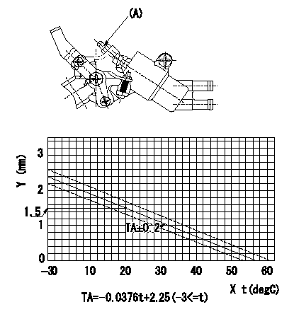
Adjustment of the W-CSD
1. Adjustment of the advance angle of the timer
(1)Determine the timer advance angle using the graph.
(2)(1) Adjust with the screw (A) so that the timer advance angle determined in the item (1) is obtained.
X = temperature t
Y = timer stroke
----------
----------
----------
----------
0000001901 W-FICD LEVER ADJUSTMENT
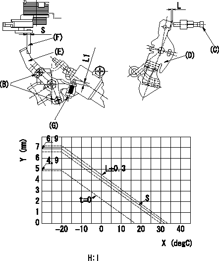
2. Adjustment of the W-FICD
(1)Insert a block gauge L2 determined from the graph below between the control lever (D) and the idling stopper bolt (C).
(2)Insert a shim S between the W-FICD lever (E) and the control lever (F). Adjust the W-FICD lever (E) so that it contacts the control lever (F) and fix it using bolt (B).
TT
Note:
a) The temperature of wax at the time of adjustment must not exceed a.
b) After completion of the adjustment, confirm that allowance for adjustment of the screw (G) is at least L1.
X:Temperature X (deg C)
Y:Control lever: dimension L (mm) (control lever position)
H:Graph, L - X graph
----------
L2=L+-0.05mm S=3+-0.05mm T=3.4~4.9N-m(0.35~0.5kgf-m) a=30degC L1=3mm
----------
L1=3++mm S=(3mm) H:L=-0.132X+4.29(-20<=X)(S=3+-0.05)
----------
L2=L+-0.05mm S=3+-0.05mm T=3.4~4.9N-m(0.35~0.5kgf-m) a=30degC L1=3mm
----------
L1=3++mm S=(3mm) H:L=-0.132X+4.29(-20<=X)(S=3+-0.05)
Information:
This Program must be administered as soon as possible. When reporting the repair, use "PI3325" as the Part Number, "7751" as the Group Number, "56" as the Warranty Claim Description Code and "T" as the SIMS Description Code. Exception: If the repair is done after failure, use "PI3325" as the Part Number, "7751" as the Group Number, "96" as the Warranty Claim Description Code, and "Z" as the SIMS Description Code.
Completion Date
February 29, 2000Termination Date
February 29, 2000Problem
Upgrade software needs to be installed on certain 3606, 3608, 3612, and 3616 diesel engines with the Marine Monitoring System (MMS) to become Y2K compatible.
Affected Product
Model & Identification Number
3606 (8RB29, 8RB656-661, 8RB669, 8RB672-673, 8RB680-688, 8RB691-00692, 8RB695-702, 8RB711-00713, 8RB715, 8RB717-718, 8RB721-723)
3608 (6MC535-536, 6MC550, 6MC561-562, 6MC582-586)
3612 (9RC230, 9RC242, 9RC247-253, 9RC256-257, 9RC259-260)
3616 (1PD289-293, 1PD295, 1PD306, 1PD308, 1PD313-336)
Parts Needed
- Dealers will need to obtain the Upgrade Files for this program.- 1 Blank formatted 1.44 MB floppy disk for Winfile Upgrade- 6 Blank formatted 1.44 MB floppy disks for InTouch 5.6B UpgradeAction Required
See the attached procedure.
Owner Notification
U.S. and Canadian owners will receive the attached Owner Notification.
Service Claim Allowances
This is a 1-hour job.
U.S. and Canadian Dealers Only - Eligible dealers may enter a Type 2 SIMS Report.
Parts Disposition
Handle the parts in accordance with your Warranty Bulletin on warranty parts handling.
MAKE EVERY EFFORT TO COMPLETE THIS PROGRAM AS SOON AS POSSIBLE.
Attach.(1-Owner Notification)(1-Rework Procedure)Copy Of Owner Notification For U.S. And Canadian Owners
Rework Procedure
Windows 3.11 Winfile Upgrade
This upgrade is necessary for Windows 3.11 to correctly date stamp files after the year 2000, The first three steps in the following procedure will be done in the office or shop.
1. Obtain the file. The file can be obtained from the Caterpillar Mailbox, SISWEB, or from the SIS disks that are released monthly. The file part number is 174-8693.2. Unzip the file. The 174-8693.exe file is a self-executing zip file. To Unzip, place the file in a known location on the hard drive. Run the file. At the dialog box type in 'A:\' where it asks for the folder to place unzipped files. Install a blank formatted disk into the A: drive. Select UNZIP or press "ENTER". This will unzip the files to the floppy drive. If your floppy drive is not 'A:' substitute your floppy drive letter for A in the above instuctions.)
3. Label the disk. This disk should be labeled "Winfile.exe Y2K Upgrade". This disk or a copy of this disk can be used to do multiple upgrades. It is not necessary to repeat steps 1-3 for each upgrade.4. Perform the upgrade. The upgrade should be done from the DOS prompt. Attach a keyboard to the MMS computer. With the MMS program running press "ALT"and "F4" at the same time. This will exit the MMS program. Press "ALT"and "F4" at the same time again and you will get a dialog box that asks you to confirm you want to end your Windows session. Press "ENTER" to confirm. Install the floppy labeled "Winfile.exe Y2K Upgrade" into the floppy drive on the MMS
Have questions with 104745-8070?
Group cross 104745-8070 ZEXEL
Mitsubishi
Mitsubishi
Mitsubishi
Mitsubishi
Mitsubishi
104745-8070
9 460 611 900
MD331231
INJECTION-PUMP ASSEMBLY
4D56
4D56