Information injection-pump assembly
BOSCH
9 460 611 564
9460611564
ZEXEL
104745-8031
1047458031
MITSUBISHI
MD325845
md325845
Rating:
Components :
| 0. | INJECTION-PUMP ASSEMBLY | 104745-8031 |
| 1. | _ | |
| 2. | FUEL INJECTION PUMP | 104645-8030 |
| 3. | NUMBER PLATE | 146971-3500 |
| 4. | _ | 479771-0520 |
| 5. | CAPSULE | |
| 6. | ADJUSTING DEVICE | |
| 7. | NOZZLE AND HOLDER ASSY | 105148-1311 |
| 8. | Nozzle and Holder | MD196607 |
| 9. | Open Pre:MPa(Kqf/cm2) | 14.7{150} |
| 10. | NOZZLE-HOLDER | 105078-0181 |
| 11. | NOZZLE | 105007-1300 |
Scheme ###:
| 1/6. | [1] | 146601-0700 | PACKING RING |
| 6. | [1] | 146100-0220 | SUPPLY PUMP |
| 9. | [1] | 146103-0100 | COVER |
| 10. | [2] | 139104-0000 | FLAT-HEAD SCREW |
| 12. | [1] | 146200-0320 | DRIVE SHAFT |
| 12/1. | [1] | 146200-0300 | DRIVE SHAFT |
| 12/2. | [1] | 146201-0000 | WOODRUFF KEY |
| 12/3. | [2] | 146202-0100 | DAMPER |
| 12/4. | [1] | 146203-0000 | TOOTHED GEAR |
| 17. | [1] | 146204-0000 | PLAIN WASHER |
| 20. | [1] | 146210-3520 | ROLLER SET |
| 24. | [1] | 146303-0100 | BEARING PIN |
| 25. | [1] | 146304-0000 | BEARING PIN |
| 26. | [1] | 146305-0000 | CLAMPING BAND |
| 27. | [1] | 146205-0000 | SLOTTED WASHER |
| 29. | [1] | 146220-2120 | CAM PLATE |
| 30. | [1] | 146600-0800 | O-RING |
| 31. | [1] | 146311-6320 | PUMP PLUNGER |
| 32. | [1] | 146301-0000 | SLIDING PIECE |
| 34. | [1] | 146312-2900 | COMPRESSION SPRING |
| 34B. | [1] | 146312-2800 | COMPRESSION SPRING |
| 34C. | [1] | 146312-3200 | COMPRESSION SPRING |
| 35/1. | [1] | 146690-3200 | SHIM D11.5&9.4T0.1 |
| 35/1. | [1] | 146690-3300 | SHIM D11.5&9.4T0.2 |
| 35/1. | [1] | 146690-3400 | SHIM D11.5&9.4T0.25 |
| 35/1. | [1] | 146690-3500 | SHIM D11.5&9.4T1.0 |
| 35/1. | [1] | 146690-4100 | SHIM D11.5&9.4T2 |
| 35/1. | [1] | 146690-4200 | SHIM D11.5&9.4T0.5 |
| 35/1. | [1] | 146690-4300 | SHIM D11.5&9.4T0.75 |
| 36. | [1] | 146600-0800 | O-RING |
| 37. | [1] | 146310-4020 | COVER |
| 38. | [2] | 146620-5000 | BLEEDER SCREW |
| 39. | [1] | 146310-0100 | COVER |
| 40. | [2] | 146620-5000 | BLEEDER SCREW |
| 41. | [1] | 146312-1900 | COMPRESSION SPRING |
| 43. | [1] | 146230-0000 | SHIM |
| 44. | [1] | 146230-0100 | PLAIN WASHER |
| 45. | [1] | 146231-0001 | SLOTTED WASHER |
| 47. | [2] | 146233-0000 | SLOTTED WASHER |
| 48/1. | [1] | 146603-0000 | SHIM D17.0&5.2T0.50 |
| 48/1. | [1] | 146603-0100 | SHIM D17.0&5.2T0.80 |
| 48/1. | [1] | 146603-0200 | SHIM D17.0&5.2T1.00 |
| 48/1. | [1] | 146603-0300 | SHIM D17.0&5.2T1.20 |
| 48/1. | [1] | 146603-0400 | SHIM D17.0&5.2T1.50 |
| 48/1. | [1] | 146603-0500 | SHIM D17.0&5.2T1.80 |
| 48/1. | [1] | 146603-0600 | SHIM D17.0&5.2T2.00 |
| 48/1. | [1] | 146690-1400 | SHIM D17&5.2T0.9 |
| 48/1. | [1] | 146690-1500 | SHIM D17&5.2T1.1 |
| 48/1. | [1] | 146690-1600 | SHIM D17&5.2T1.3 |
| 48/1. | [1] | 146690-1700 | SHIM D17&5.2T1.4 |
| 48/1. | [1] | 146690-1800 | SHIM D17&5.2T1.6 |
| 48/1. | [1] | 146690-1900 | SHIM D17&5.2T1.7 |
| 48/1. | [1] | 146690-5800 | SHIM |
| 48/1. | [1] | 146690-5900 | SHIM |
| 48/1. | [1] | 146690-6000 | SHIM |
| 48/1. | [1] | 146690-6100 | SHIM |
| 48/1. | [1] | 146690-6200 | SHIM |
| 48/1. | [1] | 146690-6300 | SHIM |
| 48/1. | [1] | 146690-6400 | SHIM |
| 48/1. | [1] | 146690-6500 | SHIM |
| 48/1. | [1] | 146690-6600 | SHIM |
| 48/1. | [1] | 146690-6700 | SHIM |
| 48/1. | [1] | 146690-6800 | SHIM |
| 48/1. | [1] | 146690-6900 | SHIM |
| 48/1. | [1] | 146690-7000 | SHIM |
| 48/1. | [1] | 146690-7100 | SHIM |
| 48/1. | [1] | 146690-7200 | SHIM |
| 48/1. | [1] | 146690-7300 | SHIM |
| 48/1. | [1] | 146690-7400 | SHIM |
| 48/1. | [1] | 146690-7500 | SHIM |
| 48/1. | [1] | 146690-7800 | SHIM |
| 49. | [2] | 146234-0020 | GUIDE PIN |
| 50. | [1] | 146401-3220 | HYDRAULIC HEAD |
| 50. | [1] | 146401-3220 | HYDRAULIC HEAD |
| 50. | [1] | 146401-3220 | HYDRAULIC HEAD |
| 51. | [1] | 146600-0000 | O-RING |
| 52/1. | [1] | 146420-0000 | SHIM D9.5&3.0T1.90 |
| 52/1. | [1] | 146420-0100 | SHIM D9.5&3.0T1.92 |
| 52/1. | [1] | 146420-0200 | SHIM D9.5&3.0T1.94 |
| 52/1. | [1] | 146420-0300 | SHIM D9.5&3.0T1.96 |
| 52/1. | [1] | 146420-0400 | SHIM D9.5&3.0T1.98 |
| 52/1. | [1] | 146420-0500 | SHIM D9.5&3.0T2.00 |
| 52/1. | [1] | 146420-0600 | SHIM D9.5&3.0T2.02 |
| 52/1. | [1] | 146420-0700 | SHIM D9.5&3.0T2.04 |
| 52/1. | [1] | 146420-0800 | SHIM D9.5&3.0T2.06 |
| 52/1. | [1] | 146420-0900 | SHIM D9.5&3.0T2.08 |
| 52/1. | [1] | 146420-1000 | SHIM D9.5&3.0T2.10 |
| 52/1. | [1] | 146420-1100 | SHIM D9.5&3.0T2.12 |
| 52/1. | [1] | 146420-1200 | SHIM D9.5&3.0T2.14 |
| 52/1. | [1] | 146420-1300 | SHIM D9.5&3.0T2.16 |
| 52/1. | [1] | 146420-1400 | SHIM D9.5&3.0T2.18 |
| 52/1. | [1] | 146420-1500 | SHIM D9.5&3.0T2.20 |
| 52/1. | [1] | 146420-1600 | SHIM D9.5&3.0T2.22 |
| 52/1. | [1] | 146420-1700 | SHIM D9.5&3.0T2.24 |
| 52/1. | [1] | 146420-1800 | SHIM D9.5&3.0T2.26 |
| 52/1. | [1] | 146420-1900 | SHIM D9.5&3.0T2.28 |
| 52/1. | [1] | 146420-2000 | SHIM D9.5&3.0T2.30 |
| 52/1. | [1] | 146420-2100 | SHIM D9.5&3.0T2.32 |
| 52/1. | [1] | 146420-2200 | SHIM D9.5&3.0T2.34 |
| 52/1. | [1] | 146420-2300 | SHIM D9.5&3.0T2.36 |
| 52/1. | [1] | 146420-2400 | SHIM D9.5&3.0T2.38 |
| 52/1. | [1] | 146420-2500 | SHIM D9.5&3.0T2.40 |
| 52/1. | [1] | 146420-2600 | SHIM D9.5&3.0T2.42 |
| 52/1. | [1] | 146420-2700 | SHIM D9.5&3.0T2.44 |
| 52/1. | [1] | 146420-2800 | SHIM D9.5&3.0T2.46 |
| 52/1. | [1] | 146420-2900 | SHIM D9.5&3.0T2.48 |
| 52/1. | [1] | 146420-3000 | SHIM D9.5&3.0T2.50 |
| 52/1. | [1] | 146420-3100 | SHIM D9.5&3.0T2.52 |
| 52/1. | [1] | 146420-3200 | SHIM D9.5&3.0T2.54 |
| 52/1. | [1] | 146420-3300 | SHIM D9.5&3.0T2.56 |
| 52/1. | [1] | 146420-3400 | SHIM D9.5&3.0T2.58 |
| 52/1. | [1] | 146420-3500 | SHIM D9.5&3.0T2.60 |
| 52/1. | [1] | 146420-3600 | SHIM D9.5&3.0T2.62 |
| 52/1. | [1] | 146420-3700 | SHIM D9.5&3.0T2.64 |
| 52/1. | [1] | 146420-3800 | SHIM D9.5&3.0T2.66 |
| 52/1. | [1] | 146420-3900 | SHIM D9.5&3.0T2.68 |
| 52/1. | [1] | 146420-4000 | SHIM D9.5&3.0T2.70 |
| 52/1. | [1] | 146420-4100 | SHIM D9.5&3.0T2.72 |
| 52/1. | [1] | 146420-4200 | SHIM D9.5&3.0T2.74 |
| 52/1. | [1] | 146420-4300 | SHIM D9.5&3.0T2.76 |
| 52/1. | [1] | 146420-4400 | SHIM D9.5&3.0T2.78 |
| 52/1. | [1] | 146420-4500 | SHIM D9.5&3.0T2.80 |
| 52/1. | [1] | 146420-4600 | SHIM D9.5&3.0T2.82 |
| 52/1. | [1] | 146420-4700 | SHIM D9.5&3.0T2.84 |
| 52/1. | [1] | 146420-4800 | SHIM D9.5&3.0T2.86 |
| 52/1. | [1] | 146420-4900 | SHIM D9.5&3.0T2.88 |
| 52/1. | [1] | 146420-5000 | SHIM D9.5&3.0T2.90 |
| 52/1. | [1] | 146420-5100 | SHIM D9.5&3.0T1.74 |
| 52/1. | [1] | 146420-5200 | SHIM D9.5&3.0T1.76 |
| 52/1. | [1] | 146420-5300 | SHIM D9.5&3.0T1.78 |
| 52/1. | [1] | 146420-5400 | SHIM D9.5&3.0T1.80 |
| 52/1. | [1] | 146420-5500 | SHIM D9.5&3.0T1.82 |
| 52/1. | [1] | 146420-5600 | SHIM D9.5&3.0T1.84 |
| 52/1. | [1] | 146420-5700 | SHIM D9.5&3.0T1.86 |
| 52/1. | [1] | 146420-5800 | SHIM D9.5&3.0T1.88 |
| 54. | [4] | 146433-0100 | GASKET D12&6.4T1.00 |
| 55. | [4] | 146430-2020 | DELIVERY-VALVE ASSEMBLY |
| 56. | [4] | 146432-0000 | COMPRESSION SPRING |
| 58. | [4] | 146440-0320 | FITTING |
| 60. | [3] | 139106-0100 | FLAT-HEAD SCREW |
| 67. | [1] | 146704-1520 | COMPENSATOR,MANIFOLD-PRES |
| 67/1. | [1] | 146805-7220 | GOVERNOR COVER |
| 67/2. | [1] | 146515-0320 | CONTROL SHAFT |
| 67/3. | [1] | 146600-0100 | O-RING |
| 67/4. | [1] | 139310-0200 | PLAIN WASHER |
| 67/14. | [1] | 146621-1700 | UNION NUT |
| 67/16. | [1] | 146526-3000 | BLEEDER SCREW |
| 67/23. | [1] | 146925-7520 | BRACKET |
| 67/24. | [2] | 010206-2240 | HEX-SOCKET-HEAD CAP SCREW |
| 67/31. | [1] | 146710-0700 | BUSHING |
| 67/32. | [1] | 146711-0000 | PLATE |
| 67/33. | [1] | 139218-0400 | UNION NUT |
| 67/34. | [1] | 146712-0700 | BEARING PIN |
| 67/35. | [1] | 146621-0300 | UNION NUT |
| 67/36. | [1] | 146600-1400 | O-RING |
| 67/37. | [1] | 146710-0100 | BUSHING |
| 67/38. | [1] | 139506-0200 | GASKET D8.9&6.8T1.00 |
| 67/39. | [1] | 146620-0300 | CAPSULE |
| 67/40. | [1] | 026512-1540 | GASKET D15.4&12.2T1.50 |
| 67/41. | [1] | 146713-4300 | ADJUSTING PIN |
| 67/42. | [2] | 146714-0200 | PLATE |
| 67/43. | [1] | 146715-0300 | DIAPHRAGM |
| 67/44. | [1] | 139306-0100 | LOCKING WASHER |
| 67/45. | [1] | 013030-6040 | UNION NUT M6P1H3.6 |
| 67/46. | [1] | 146716-0000 | UNION NUT |
| 67/47. | [1] | 146717-2900 | COILED SPRING |
| 67/48/1. | [1] | 146720-3000 | SPACER BUSHING L3.7 |
| 67/48/1. | [1] | 146720-3100 | SPACER BUSHING L3.9 |
| 67/48/1. | [1] | 146720-3200 | SPACER BUSHING L4.1 |
| 67/48/1. | [1] | 146720-3300 | SPACER BUSHING L4.3 |
| 67/48/1. | [1] | 146720-3400 | SPACER BUSHING L4.5 |
| 67/48/1. | [1] | 146720-3500 | SPACER BUSHING L4.7 |
| 67/48/1. | [1] | 146720-3600 | SPACER BUSHING L4.9 |
| 67/48/1. | [1] | 146720-3700 | SPACER BUSHING L5.1 |
| 67/48/1. | [1] | 146720-3800 | SPACER BUSHING L5.3 |
| 67/48/1. | [1] | 146720-3900 | SPACER BUSHING L5.5 |
| 67/48/1. | [1] | 146720-4000 | SPACER BUSHING L5.7 |
| 67/48/1. | [1] | 146720-4100 | SPACER BUSHING L5.9 |
| 67/48/1. | [1] | 146720-4200 | SPACER BUSHING L6.1 |
| 67/48/1. | [1] | 146720-4300 | SPACER BUSHING L6.3 |
| 67/48/1. | [1] | 146720-4400 | SPACER BUSHING L6.5 |
| 67/48/1. | [1] | 146720-8900 | SPACER BUSHING L6.7 |
| 67/48/1. | [1] | 146720-9000 | SPACER BUSHING L6.9 |
| 67/48/1. | [1] | 146720-9100 | SPACER BUSHING L7.1 |
| 67/48/1. | [1] | 146720-9200 | SPACER BUSHING L7.3 |
| 67/48/1. | [1] | 146720-9300 | SPACER BUSHING L7.5 |
| 67/48/1. | [1] | 146720-9400 | SPACER BUSHING L7.7 |
| 67/48/1. | [1] | 146720-9500 | SPACER BUSHING L7.9 |
| 67/48/1. | [1] | 146720-9600 | SPACER BUSHING L8.1 |
| 67/48/1. | [1] | 146720-9700 | SPACER BUSHING L8.3 |
| 67/48/1. | [1] | 146720-9800 | SPACER BUSHING L8.5 |
| 67/48/1. | [1] | 146720-9900 | SPACER BUSHING L3.6 |
| 67/48/1. | [1] | 146725-0000 | SPACER BUSHING L3.8 |
| 67/48/1. | [1] | 146725-0100 | SPACER BUSHING L4.0 |
| 67/48/1. | [1] | 146725-0200 | SPACER BUSHING L4.2 |
| 67/48/1. | [1] | 146725-0300 | SPACER BUSHING L4.4 |
| 67/48/1. | [1] | 146725-0400 | SPACER BUSHING L4.6 |
| 67/48/1. | [1] | 146725-0500 | SPACER BUSHING L4.8 |
| 67/48/1. | [1] | 146725-0600 | SPACER BUSHING L5.0 |
| 67/48/1. | [1] | 146725-0700 | SPACER BUSHING L5.2 |
| 67/48/1. | [1] | 146725-0800 | SPACER BUSHING L5.4 |
| 67/48/1. | [1] | 146725-0900 | SPACER BUSHING L5.6 |
| 67/48/1. | [1] | 146725-1000 | SPACER BUSHING L5.8 |
| 67/48/1. | [1] | 146725-1100 | SPACER BUSHING L6.0 |
| 67/48/1. | [1] | 146725-1200 | SPACER BUSHING L6.2 |
| 67/48/1. | [1] | 146725-1300 | SPACER BUSHING L6.4 |
| 67/48/1. | [1] | 146725-1400 | SPACER BUSHING L6.6 |
| 67/48/1. | [1] | 146725-1500 | SPACER BUSHING L6.8 |
| 67/48/1. | [1] | 146725-1600 | SPACER BUSHING L7.0 |
| 67/48/1. | [1] | 146725-1700 | SPACER BUSHING L7.2 |
| 67/48/1. | [1] | 146725-1800 | SPACER BUSHING L7.4 |
| 67/48/1. | [1] | 146725-1900 | SPACER BUSHING L7.6 |
| 67/48/1. | [1] | 146725-2000 | SPACER BUSHING L7.8 |
| 67/48/1. | [1] | 146725-2100 | SPACER BUSHING L8.0 |
| 67/48/1. | [1] | 146725-2200 | SPACER BUSHING L8.2 |
| 67/48/1. | [1] | 146725-2300 | SPACER BUSHING L8.4 |
| 67/48/1. | [1] | 146725-2400 | SPACER BUSHING L8.6 |
| 67/49. | [1] | 146721-3720 | COVER |
| 67/50. | [1] | 146722-0200 | FLAT-HEAD SCREW |
| 67/51. | [1] | 146600-0300 | O-RING |
| 67/53. | [1] | 013020-6040 | UNION NUT M6P1H5 |
| 67/54. | [2] | 139006-4700 | BLEEDER SCREW |
| 67/55. | [2] | 139006-4600 | BLEEDER SCREW |
| 67/56. | [1] | 146723-0200 | CONTROL LEVER |
| 67/57. | [1] | 146712-0100 | BEARING PIN |
| 67/58. | [2] | 146620-0600 | CAPSULE |
| 67/59. | [2] | 026506-1040 | GASKET D9.9&6.2T1 |
| 67/60. | [1] | 146724-0300 | ELEMENT |
| 67/61. | [1] | 146724-0600 | CAPSULE |
| 67/78. | [1] | 146600-4400 | SEAL RING |
| 67/96. | [1] | 146659-7220 | CLAMPING BAND |
| 67/102. | [1] | 146932-6922 | BRACKET |
| 67/200. | [1] | 139308-0300 | PLAIN WASHER |
| 67/201. | [1] | 146545-3400 | THREADED PIN L53.00 |
| 67/201B. | [1] | 146545-3500 | THREADED PIN L55.00 |
| 67/201C. | [1] | 146545-3600 | THREADED PIN L57.00 |
| 67/202. | [1] | 139208-0900 | UNION NUT |
| 67/203. | [1] | 146600-1200 | O-RING |
| 72. | [1] | 146830-7120 | CONTROL LEVER |
| 72B. | [1] | 146830-7220 | CONTROL LEVER |
| 72C. | [1] | 146831-9120 | CONTROL LEVER |
| 72D. | [1] | 146831-9220 | CONTROL LEVER |
| 73. | [1] | 014110-6440 | LOCKING WASHER |
| 75. | [1] | 013020-6040 | UNION NUT M6P1H5 |
| 95. | [1] | 146550-1620 | FULCRUM LEVER |
| 104. | [2] | 146568-0000 | SLOTTED SPRING PIN |
| 105. | [2] | 026508-1140 | GASKET D11.4&8.2T1 |
| 106. | [2] | 146588-0500 | COILED SPRING |
| 107. | [1] | 146569-0300 | UNION NUT |
| 108. | [1] | 146570-0420 | GOVERNOR SHAFT |
| 109. | [1] | 146600-0400 | O-RING |
| 110/1. | [1] | 146571-0000 | SHIM D20.2&8.3T1.05 |
| 110/1. | [1] | 146571-0100 | SHIM D20.2&8.3T1.25 |
| 110/1. | [1] | 146571-0200 | SHIM D20.2&8.3T1.45 |
| 110/1. | [1] | 146571-0300 | SHIM D20.2&8.3T1.65 |
| 110/1. | [1] | 146571-0400 | SHIM D20.2&8.3T1.85 |
| 110/1. | [1] | 146571-0500 | SHIM D20.2&8.3T1.15 |
| 110/1. | [1] | 146571-0600 | SHIM D20.2&8.3T1.35 |
| 110/1. | [1] | 146571-0700 | SHIM D20.2&8.3T1.55 |
| 110/1. | [1] | 146571-0800 | SHIM D20.2&8.3T1.75 |
| 111. | [1] | 146602-0600 | PLAIN WASHER D20&8.4T1.40 |
| 112. | [1] | 146572-0020 | FLYWEIGHT ASSEMBLY |
| 114. | [1] | 146602-0500 | PLAIN WASHER D17&6.4T1.60 |
| 115. | [1] | 146875-8300 | SLIDING SLEEVE |
| 116. | [1] | 146576-0000 | SEALING CAP |
| 117/1. | [1] | 146577-1800 | PLUG L2.10 |
| 117/1. | [1] | 146577-1900 | PLUG L2.30 |
| 117/1. | [1] | 146577-2000 | PLUG L2.50 |
| 117/1. | [1] | 146577-2100 | PLUG L2.70 |
| 117/1. | [1] | 146577-2200 | PLUG L2.90 |
| 117/1. | [1] | 146577-2300 | PLUG L3.10 |
| 117/1. | [1] | 146577-2400 | PLUG L3.30 |
| 117/1. | [1] | 146577-2500 | PLUG L3.50 |
| 117/1. | [1] | 146577-2600 | PLUG L3.70 |
| 117/1. | [1] | 146577-2700 | PLUG L3.90 |
| 117/1. | [1] | 146577-2800 | PLUG L4.10 |
| 117/1. | [1] | 146577-2900 | PLUG L4.30 |
| 117/1. | [1] | 146577-3000 | PLUG L4.50 |
| 117/1. | [1] | 146577-3100 | PLUG L4.70 |
| 117/1. | [1] | 146577-3200 | PLUG L4.90 |
| 117/1. | [1] | 146577-3300 | PLUG L5.10 |
| 117/1. | [1] | 146577-6700 | PLUG L2.2 |
| 117/1. | [1] | 146577-6800 | PLUG L2.4 |
| 117/1. | [1] | 146577-6900 | PLUG L2.6 |
| 117/1. | [1] | 146577-7000 | PLUG L2.8 |
| 117/1. | [1] | 146577-7100 | PLUG L3.0 |
| 117/1. | [1] | 146577-7200 | PLUG L3.2 |
| 117/1. | [1] | 146577-7300 | PLUG L3.4 |
| 117/1. | [1] | 146577-7400 | PLUG L3.6 |
| 117/1. | [1] | 146577-7500 | PLUG L3.8 |
| 117/1. | [1] | 146577-7600 | PLUG L4.0 |
| 117/1. | [1] | 146577-7700 | PLUG L4.2 |
| 117/1. | [1] | 146577-7800 | PLUG L4.4 |
| 117/1. | [1] | 146577-7900 | PLUG L4.6 |
| 117/1. | [1] | 146577-8000 | PLUG L4.8 |
| 117/1. | [1] | 146577-8100 | PLUG L5.0 |
| 117/1. | [1] | 146877-0000 | PLUG L5.2 |
| 117/1. | [1] | 146877-0100 | PLUG L5.3 |
| 117/1. | [1] | 146877-0200 | PLUG L5.4 |
| 117/1. | [1] | 146877-0300 | PLUG L5.5 |
| 117/1. | [1] | 146877-4700 | PLUG |
| 117/1. | [1] | 146877-4800 | PLUG |
| 117/1. | [1] | 146877-4900 | PLUG |
| 117/1. | [1] | 146877-5000 | PLUG |
| 120. | [1] | 146879-0220 | RETAINING PIN |
| 122. | [1] | 146580-2300 | GOVERNOR SPRING |
| 123. | [4] | 146620-0500 | HEX-SOCKET-HEAD CAP SCREW |
| 130. | [1] | 146421-0020 | CAPSULE |
| 130/2. | [1] | 026508-1140 | GASKET D11.4&8.2T1 |
| 130/3. | [1] | 146422-0000 | BLEEDER SCREW |
| 130/4. | [1] | 146600-0500 | O-RING |
| 133. | [1] | 146600-0600 | O-RING |
| 134. | [1] | 146600-0700 | O-RING |
| 135. | [1] | 146110-0220 | CONTROL VALVE |
| 135/5. | [1] | 146114-0000 | SPRING WASHER |
| 136. | [1] | 146120-0020 | OVER FLOW VALVE |
| 137. | [2] | 139512-0500 | GASKET |
| 138. | [1] | 146665-4520 | INLET UNION |
| 200. | [1] | 146206-0100 | COILED SPRING |
| 205. | [1] | 029470-4030 | WOODRUFF KEY |
| 217. | [1] | 146542-5300 | SLOTTED WASHER |
| 218. | [1] | 146592-2500 | COILED SPRING |
| 219. | [1] | 146541-3000 | BUSHING |
| 220. | [1] | 146592-2600 | COILED SPRING |
| 224. | [1] | 139006-4400 | BLEEDER SCREW |
| 230. | [1] | 146613-2500 | BRACKET |
| 231. | [1] | 139006-4400 | BLEEDER SCREW |
| 232. | [1] | 146931-3200 | BRACKET |
| 234. | [1] | 139006-4800 | BLEEDER SCREW |
| 235. | [1] | 146931-6100 | BRACKET |
| 237. | [1] | 146620-0200 | HEX-SOCKET-HEAD CAP SCREW |
| 240. | [1] | 146688-0120 | PULLING ELECTROMAGNET |
| 240/8. | [1] | 146600-1700 | O-RING |
| 242. | [1] | 407911-1410 | CONTROL UNIT |
| 243. | [1] | 146621-4900 | UNION NUT |
| 245. | [3] | 139512-0500 | GASKET |
| 246. | [1] | 139812-1900 | EYE BOLT |
| 247. | [1] | 146666-8520 | INLET UNION |
| 248. | [1] | 146614-0200 | SPACER BUSHING |
| 251. | [1] | 146125-0101 | FILTER |
| 252. | [1] | 146125-0200 | COILED SPRING |
| 275. | [1] | 146612-4800 | BRACKET |
| 276. | [2] | 010010-1640 | BLEEDER SCREW M10P1.5L16 4T |
| 280. | [1] | 146361-4120 | START ADVANCE ASSY |
| 281. | [1] | 146600-0800 | O-RING |
| 286. | [1] | 020106-3540 | BLEEDER SCREW |
| 287. | [1] | 014010-6140 | PLAIN WASHER D13&6.5T1 |
| 288. | [1] | 146931-6300 | BRACKET |
| 360. | [1] | 146663-1700 | BUSHING |
| 361. | [1] | 146649-8900 | CAP |
| 362. | [2] | 146620-8402 | BLEEDER SCREW |
| 800S. | [1] | 146018-4820 | PUMP HOUSING |
| 800S/1/6. | [1] | 146601-0700 | PACKING RING |
| 800S/1/6. | [1] | 146601-0700 | PACKING RING |
| 804S. | [1] | 146232-0320 | COMPRESSION SPRING |
| 805S. | [1] | 146574-0120 | PARTS SET |
| 810S. | [1] | 146600-1120 | REPAIR SET |
| 821S. | [1] | 146210-5720 | ROLLER SET |
| 835S. | [1] | 146598-1000 | CAP |
| 836S/1. | [1] | 146598-0600 | CAP L18 |
| 836S/1. | [1] | 146598-0700 | CAP L21 |
| 836S/1. | [1] | 146598-0800 | CAP L24 |
| 836S/1. | [1] | 146598-0900 | CAP L27 |
| 903. | [1] | 479771-0520 | PULSE GENERATOR |
| 906. | [1] | 146971-3500 | NAMEPLATE |
| 910S. | [1] | 146600-4220 | PARTS SET |
| 910S. | [1] | 146600-4220 | PARTS SET |
| 911S. | [1] | 479771-0520 | PULSE GENERATOR |
| 912S. | [1] | 026508-1140 | GASKET D11.4&8.2T1 |
| 913S. | [1] | 146422-0000 | BLEEDER SCREW |
| 914S. | [1] | 146699-0620 | VALVE SET |
| 914S. | [1] | 146699-0620 | VALVE SET |
| 914S. | [1] | 146699-0620 | VALVE SET |
| 916S. | [1] | 025804-1610 | WOODRUFF KEY |
Include in #2:
104745-8031
as INJECTION-PUMP ASSEMBLY
Cross reference number
BOSCH
9 460 611 564
9460611564
ZEXEL
104745-8031
1047458031
MITSUBISHI
MD325845
md325845
Zexel num
Bosch num
Firm num
Name
104745-8031
9 460 611 564
MD325845 MITSUBISHI
INJECTION-PUMP ASSEMBLY
4D56 K 11CJ INJECTION PUMP ASSY VE4 VE
4D56 K 11CJ INJECTION PUMP ASSY VE4 VE
Calibration Data:
Adjustment conditions
Test oil
1404 Test oil ISO4113orSAEJ967d
1404 Test oil ISO4113orSAEJ967d
Test oil temperature
degC
45
45
50
Nozzle
105780-0060
Bosch type code
NP-DN0SD1510
Nozzle holder
105780-2150
Opening pressure
MPa
13
13
13.3
Opening pressure
kgf/cm2
133
133
136
Injection pipe
157805-7320
Injection pipe
Inside diameter - outside diameter - length (mm) mm 2-6-450
Inside diameter - outside diameter - length (mm) mm 2-6-450
Joint assembly
157641-4720
Tube assembly
157641-4020
Transfer pump pressure
kPa
20
20
20
Transfer pump pressure
kgf/cm2
0.2
0.2
0.2
Direction of rotation (viewed from drive side)
Right R
Right R
Injection timing adjustment
Pump speed
r/min
750
750
750
Boost pressure
kPa
0
0
0
Boost pressure
mmHg
0
0
0
Average injection quantity
mm3/st.
52.6
52.1
53.1
Difference in delivery
mm3/st.
4
Basic
*
Oil temperature
degC
50
48
52
Remarks
NA
NA
Injection timing adjustment_02
Pump speed
r/min
750
750
750
Boost pressure
kPa
44
42.7
45.3
Boost pressure
mmHg
330
320
340
Average injection quantity
mm3/st.
62.6
62.1
63.1
Difference in delivery
mm3/st.
5
Basic
*
Oil temperature
degC
50
48
52
Remarks
CBS
CBS
Injection timing adjustment_03
Pump speed
r/min
1250
1250
1250
Boost pressure
kPa
73.3
72
74.6
Boost pressure
mmHg
550
540
560
Average injection quantity
mm3/st.
76.6
76.1
77.1
Difference in delivery
mm3/st.
6
Basic
*
Oil temperature
degC
50
48
52
Remarks
Full
Full
Injection timing adjustment_04
Pump speed
r/min
750
750
750
Boost pressure
kPa
0
0
0
Boost pressure
mmHg
0
0
0
Average injection quantity
mm3/st.
52.6
51.6
53.6
Oil temperature
degC
50
48
52
Injection timing adjustment_05
Pump speed
r/min
750
750
750
Boost pressure
kPa
44
42.7
45.3
Boost pressure
mmHg
330
320
340
Average injection quantity
mm3/st.
62.6
61.6
63.6
Basic
*
Oil temperature
degC
50
48
52
Remarks
CBS
CBS
Injection timing adjustment_06
Pump speed
r/min
1000
1000
1000
Boost pressure
kPa
73.3
72
74.6
Boost pressure
mmHg
550
540
560
Average injection quantity
mm3/st.
77
74.5
79.5
Oil temperature
degC
50
48
52
Injection timing adjustment_07
Pump speed
r/min
1250
1250
1250
Boost pressure
kPa
73.3
72
74.6
Boost pressure
mmHg
550
540
560
Average injection quantity
mm3/st.
76.6
75.6
77.6
Difference in delivery
mm3/st.
6.5
Basic
*
Oil temperature
degC
50
48
52
Remarks
Full
Full
Injection timing adjustment_08
Pump speed
r/min
2100
2100
2100
Boost pressure
kPa
73.3
72
74.6
Boost pressure
mmHg
550
540
560
Average injection quantity
mm3/st.
65
62.5
67.5
Oil temperature
degC
52
50
54
Injection quantity adjustment
Pump speed
r/min
2650
2650
2650
Boost pressure
kPa
73.3
72
74.6
Boost pressure
mmHg
550
540
560
Average injection quantity
mm3/st.
27.9
24.9
30.9
Difference in delivery
mm3/st.
8.5
Basic
*
Oil temperature
degC
55
52
58
Injection quantity adjustment_02
Pump speed
r/min
2650
2650
2650
Boost pressure
kPa
73.3
72
74.6
Boost pressure
mmHg
550
540
560
Average injection quantity
mm3/st.
27.9
22.9
32.9
Difference in delivery
mm3/st.
9
Basic
*
Oil temperature
degC
55
52
58
Injection quantity adjustment_03
Pump speed
r/min
2950
2950
2950
Boost pressure
kPa
73.3
72
74.6
Boost pressure
mmHg
550
540
560
Average injection quantity
mm3/st.
5
Oil temperature
degC
55
52
58
Governor adjustment
Pump speed
r/min
375
375
375
Boost pressure
kPa
0
0
0
Boost pressure
mmHg
0
0
0
Average injection quantity
mm3/st.
19.4
17.9
20.9
Difference in delivery
mm3/st.
2
Basic
*
Oil temperature
degC
48
46
50
Governor adjustment_02
Pump speed
r/min
375
375
375
Boost pressure
kPa
0
0
0
Boost pressure
mmHg
0
0
0
Average injection quantity
mm3/st.
19.4
17.4
21.4
Difference in delivery
mm3/st.
2.5
Basic
*
Oil temperature
degC
48
46
50
Governor adjustment_03
Pump speed
r/min
750
750
750
Boost pressure
kPa
0
0
0
Boost pressure
mmHg
0
0
0
Average injection quantity
mm3/st.
8
Oil temperature
degC
50
48
52
Timer adjustment
Pump speed
r/min
100
100
100
Boost pressure
kPa
0
0
0
Boost pressure
mmHg
0
0
0
Average injection quantity
mm3/st.
75
65
85
Basic
*
Oil temperature
degC
48
46
50
Remarks
IDLE
IDLE
Timer adjustment_02
Pump speed
r/min
100
100
100
Boost pressure
kPa
0
0
0
Boost pressure
mmHg
0
0
0
Average injection quantity
mm3/st.
75
65
85
Oil temperature
degC
48
46
50
Remarks
IDLE
IDLE
Speed control lever angle
Pump speed
r/min
375
375
375
Boost pressure
kPa
0
0
0
Boost pressure
mmHg
0
0
0
Average injection quantity
mm3/st.
0
0
0
Oil temperature
degC
48
46
50
Remarks
Magnet OFF at idling position
Magnet OFF at idling position
0000000901
Pump speed
r/min
1250
1250
1250
Boost pressure
kPa
73.3
72
74.6
Boost pressure
mmHg
550
540
560
Overflow quantity
cm3/min
420
290
550
Oil temperature
degC
50
48
52
Stop lever angle
Pump speed
r/min
1250
1250
1250
Boost pressure
kPa
73.3
72
74.6
Boost pressure
mmHg
550
540
560
Pressure
kPa
549
520
578
Pressure
kgf/cm2
5.6
5.3
5.9
Basic
*
Oil temperature
degC
50
48
52
Stop lever angle_02
Pump speed
r/min
500
500
500
Boost pressure
kPa
73.3
72
74.6
Boost pressure
mmHg
550
540
560
Pressure
kPa
373
334
412
Pressure
kgf/cm2
3.8
3.4
4.2
Oil temperature
degC
48
46
50
Stop lever angle_03
Pump speed
r/min
1250
1250
1250
Boost pressure
kPa
73.3
72
74.6
Boost pressure
mmHg
550
540
560
Pressure
kPa
549
510
588
Pressure
kgf/cm2
5.6
5.2
6
Basic
*
Oil temperature
degC
50
48
52
Stop lever angle_04
Pump speed
r/min
2100
2100
2100
Boost pressure
kPa
73.3
72
74.6
Boost pressure
mmHg
550
540
560
Pressure
kPa
736
697
775
Pressure
kgf/cm2
7.5
7.1
7.9
Oil temperature
degC
52
50
54
0000001101
Pump speed
r/min
1250
1250
1250
Boost pressure
kPa
73.3
72
74.6
Boost pressure
mmHg
550
540
560
Timer stroke
mm
4.6
4.4
4.8
Basic
*
Oil temperature
degC
50
48
52
_02
Pump speed
r/min
500
500
500
Boost pressure
kPa
73.3
72
74.6
Boost pressure
mmHg
550
540
560
Timer stroke
mm
1.2
0.6
1.8
Oil temperature
degC
48
46
50
_03
Pump speed
r/min
1000
1000
1000
Boost pressure
kPa
73.3
72
74.6
Boost pressure
mmHg
550
540
560
Timer stroke
mm
3.5
2.9
4.1
Oil temperature
degC
50
48
52
_04
Pump speed
r/min
1250
1250
1250
Boost pressure
kPa
73.3
72
74.6
Boost pressure
mmHg
550
540
560
Timer stroke
mm
4.6
4.2
5
Basic
*
Oil temperature
degC
50
48
52
_05
Pump speed
r/min
1500
1500
1500
Boost pressure
kPa
73.3
72
74.6
Boost pressure
mmHg
550
540
560
Timer stroke
mm
5.6
5
6.2
Oil temperature
degC
50
48
52
_06
Pump speed
r/min
2100
2100
2100
Boost pressure
kPa
73.3
72
74.6
Boost pressure
mmHg
550
540
560
Timer stroke
mm
7.8
7.2
8.4
Oil temperature
degC
52
50
54
0000001201
Max. applied voltage
V
8
8
8
Test voltage
V
13
12
14
0000001401
Pump speed
r/min
1250
1250
1250
Boost pressure
kPa
73.3
72
74.6
Boost pressure
mmHg
550
540
560
Average injection quantity
mm3/st.
48
47.5
48.5
Timer stroke TA
mm
3.9
3.7
4.1
Timer stroke variation dT
mm
0.7
0.7
0.7
Basic
*
Oil temperature
degC
50
48
52
_02
Pump speed
r/min
1250
1250
1250
Boost pressure
kPa
73.3
72
74.6
Boost pressure
mmHg
550
540
560
Average injection quantity
mm3/st.
48
47
49
Timer stroke TA
mm
3.9
3.5
4.3
Basic
*
Oil temperature
degC
50
48
52
_03
Pump speed
r/min
1250
1250
1250
Boost pressure
kPa
73.3
72
74.6
Boost pressure
mmHg
550
540
560
Average injection quantity
mm3/st.
32
31
33
Timer stroke TA
mm
2.5
1.9
3.1
Oil temperature
degC
50
48
52
Timing setting
K dimension
mm
3.3
3.2
3.4
KF dimension
mm
5.8
5.7
5.9
MS dimension
mm
1.2
1.1
1.3
BCS stroke
mm
5.7
5.5
5.9
Control lever angle alpha
deg.
59
55
63
Control lever angle beta
deg.
42
37
47
Test data Ex:
0000001801 W-CSD ADJUSTMENT
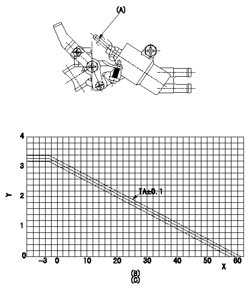
Adjustment of the W-CSD
Adjustment of the timer advance angle
Adjust screw (A) so that the timer stroke is the value determined from the graph (B).
(C) graph TA = -0.0526t+3.14 (-3<=t(deg C))
X:Temperature t (deg C)
Y:Timer stroke TA (mm)
----------
----------
----------
----------
0000001901 W-FICD LEVER ADJUSTMENT
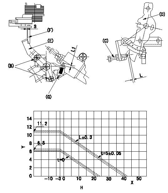
W-FICD adjustment
(1)Insert a block gauge L+-0.05 (mm) determined from the graph H between the control lever (D) and the idling stopper bolt (C).
(2)Insert a shim S+-0.5 (mm) between the W-FICD lever (E) and the control lever (F). Adjust the W-FICD lever (E) so that it contacts the control lever (F) and fix it using bolt (B). (Tighten to torque T.)
(3)The temperature of the wax at adjustment must not exceed a.
(4)After completing adjustment, confirm that screw (G) has an adjusting margin of at least L1.
Y:Control lever L (mm)
X:Temperature t (deg C)
H:Block gauge thickness L diagram
----------
S=5mm L=-0.256t+10.39(-3<=t)(S=5+-0.05) L1=3mm T=3.4~4.9N-m(0.35~0.5kgf-m) a=30degC
----------
S=5mm L1=3mm H=L=-0.256t+10.39(-3<=t)(S=5+-0.05)
----------
S=5mm L=-0.256t+10.39(-3<=t)(S=5+-0.05) L1=3mm T=3.4~4.9N-m(0.35~0.5kgf-m) a=30degC
----------
S=5mm L1=3mm H=L=-0.256t+10.39(-3<=t)(S=5+-0.05)
Information:
This Program must be administered as soon as possible. When reporting the repair, use "PI3147" as the Part Number, "7751" as the Group Number, "56" as the Warranty Claim Description Code and "T" as the SIMS Description Code. Exception: If the repair is done after failure, use "PI3147" as the Part Number, "7751" as the Group Number, "96" as the Warranty Claim Description Code, and "Z" as the SIMS Description Code.
Refer to your Warranty Bulletin for detailed information with regard to Product Improvement Programs.
Completion Date
November 30, 1998Termination Date
November 30, 1998Problem
Certain 3116 and 3126 2-Valve Engines built from January 28 through February 6, 1998 with CBS heads are suspect to have improper installation of the brass injector sleeve.
Affected Product
Model & Identification Number
3116 (2WG6414-6426 5EN01269, 5EN1270, 5EN1273-1280, 5EN1282 4KG7773-7795 4KG31268NM3029-3043 9ZR771-774 )
Parts Needed
1 - 1192940 Gasket* - 1193061 Sleeve*(as required)Action Required
See the attached procedure.
Owner Notification
U.S. and Canadian owners will receive the attached Owner Notification.
Service Claim Allowances
Parts Disposition
Handle the parts in accordance with your Warranty Bulletin on warranty parts handling.
MAKE EVERY EFFORT TO COMPLETE THIS PROGRAM AS SOON AS POSSIBLE.
Attach.(1-Owner Notification)(2-Rework Procedure)Copy Of Owner Notification For U.S. And Canadian Owners
Rework Procedure
1. Check to see if the head is supplied by CBS or Gosselies. The part number is located on the front of the head on the governor side beside the lifting eye, just above the front cover. In Marine applications, it is best viewed using a light to look between the expansion tank and heat exchanger.If it is a dot-matrix, then the head is from Gosselies. If the part number is stamped, then it is from CBS.
If the head is from Gosselies (dot-matrix part number), then the engine is good and no further work is needed.
If the head is from CBS (Stamped part number) then further inspection/rework is required.
2. If the head is from CBS, remove the valve cover.3. Using a sliding caliper, align the caliper vertically using the edge of the injector spring, measure and record the distance from the timing ledge on the injector to the top face of the head for each cylinder. This measurement will be in the range of 8.39 mm but can vary from engine to engine.4. If the variation from cylinder to cylinder on the same engine is less than 0.40 mm, then the engine is good. Re-install the valve cover. No further inspection is necessary.5. If the variation from cylinder to cylinder on the same engine is greater than 0.40 mm, recheck to verify measurements, if the difference is still greater than 0.40 mm, proceed to Step 6.6. Remove all (6) injectors. Using a depth gage with flat end and a 0.75 inch diameter steel ball dropped into the sleeve, check and record the distance from the top face of the head to the top of the steel ball. This measurement should be 2.583 0.18 inches (65.61 0.46 mm).7. Remove the injector sleeve on any cylinder that the measurement from step 6 is less than 2.565 inch (65.15 mm) and
Have questions with 104745-8031?
Group cross 104745-8031 ZEXEL
Mitsubishi
Mitsubishi
Mitsubishi
104745-8031
9 460 611 564
MD325845
INJECTION-PUMP ASSEMBLY
4D56
4D56