Information injection-pump assembly
BOSCH
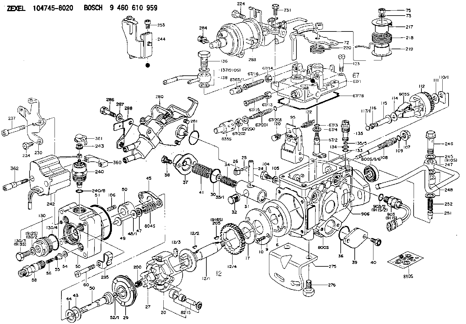
9 460 610 959
9460610959
ZEXEL
104745-8020
1047458020
MITSUBISHI
MD325844
md325844
Rating:
Components :
| 0. | INJECTION-PUMP ASSEMBLY | 104745-8020 |
| 1. | _ | |
| 2. | FUEL INJECTION PUMP | 104645-8020 |
| 3. | NUMBER PLATE | 146959-9200 |
| 4. | _ | 146672-2820 |
| 5. | CAPSULE | |
| 6. | ADJUSTING DEVICE | |
| 7. | NOZZLE AND HOLDER ASSY | 105148-1311 |
| 8. | Nozzle and Holder | MD196607 |
| 9. | Open Pre:MPa(Kqf/cm2) | 14.7{150} |
| 10. | NOZZLE-HOLDER | 105078-0181 |
| 11. | NOZZLE | 105007-1300 |
Scheme ###:
| 1/6. | [1] | 146601-0700 | PACKING RING |
| 6. | [1] | 146100-0220 | SUPPLY PUMP |
| 9. | [1] | 146103-0100 | COVER |
| 10. | [2] | 139104-0000 | FLAT-HEAD SCREW |
| 12. | [1] | 146200-0320 | DRIVE SHAFT |
| 12/1. | [1] | 146200-0300 | DRIVE SHAFT |
| 12/2. | [1] | 146201-0000 | WOODRUFF KEY |
| 12/3. | [2] | 146202-0100 | DAMPER |
| 12/4. | [1] | 146203-0000 | TOOTHED GEAR |
| 17. | [1] | 146204-0000 | PLAIN WASHER |
| 20. | [1] | 146210-3520 | ROLLER SET |
| 24. | [1] | 146303-0100 | BEARING PIN |
| 25. | [1] | 146304-0000 | BEARING PIN |
| 26. | [1] | 146305-0000 | CLAMPING BAND |
| 27. | [1] | 146205-0000 | SLOTTED WASHER |
| 29. | [1] | 146220-2120 | CAM PLATE |
| 30. | [1] | 146600-0800 | O-RING |
| 31. | [1] | 146311-6520 | PUMP PLUNGER |
| 32. | [1] | 146301-0000 | SLIDING PIECE |
| 34. | [1] | 146312-2800 | COMPRESSION SPRING |
| 34B. | [1] | 146312-2900 | COMPRESSION SPRING |
| 34C. | [1] | 146312-2700 | COMPRESSION SPRING |
| 35/1. | [1] | 146690-3200 | SHIM D11.5&9.4T0.1 |
| 35/1. | [1] | 146690-3300 | SHIM D11.5&9.4T0.2 |
| 35/1. | [1] | 146690-3400 | SHIM D11.5&9.4T0.25 |
| 35/1. | [1] | 146690-3500 | SHIM D11.5&9.4T1.0 |
| 35/1. | [1] | 146690-4100 | SHIM D11.5&9.4T2 |
| 35/1. | [1] | 146690-4200 | SHIM D11.5&9.4T0.5 |
| 35/1. | [1] | 146690-4300 | SHIM D11.5&9.4T0.75 |
| 36. | [1] | 146600-0800 | O-RING |
| 37. | [1] | 146310-4020 | COVER |
| 38. | [2] | 146620-5000 | BLEEDER SCREW |
| 39. | [1] | 146310-0100 | COVER |
| 40. | [2] | 146620-5000 | BLEEDER SCREW |
| 41. | [1] | 146312-1900 | COMPRESSION SPRING |
| 43. | [1] | 146230-0000 | SHIM |
| 44. | [1] | 146230-0100 | PLAIN WASHER |
| 45. | [1] | 146231-0001 | SLOTTED WASHER |
| 47. | [2] | 146233-0000 | SLOTTED WASHER |
| 48/1. | [1] | 146603-0000 | SHIM D17.0&5.2T0.50 |
| 48/1. | [1] | 146603-0100 | SHIM D17.0&5.2T0.80 |
| 48/1. | [1] | 146603-0200 | SHIM D17.0&5.2T1.00 |
| 48/1. | [1] | 146603-0300 | SHIM D17.0&5.2T1.20 |
| 48/1. | [1] | 146603-0400 | SHIM D17.0&5.2T1.50 |
| 48/1. | [1] | 146603-0500 | SHIM D17.0&5.2T1.80 |
| 48/1. | [1] | 146603-0600 | SHIM D17.0&5.2T2.00 |
| 48/1. | [1] | 146690-1400 | SHIM D17&5.2T0.9 |
| 48/1. | [1] | 146690-1500 | SHIM D17&5.2T1.1 |
| 48/1. | [1] | 146690-1600 | SHIM D17&5.2T1.3 |
| 48/1. | [1] | 146690-1700 | SHIM D17&5.2T1.4 |
| 48/1. | [1] | 146690-1800 | SHIM D17&5.2T1.6 |
| 48/1. | [1] | 146690-1900 | SHIM D17&5.2T1.7 |
| 48/1. | [1] | 146690-5800 | SHIM |
| 48/1. | [1] | 146690-5900 | SHIM |
| 48/1. | [1] | 146690-6000 | SHIM |
| 48/1. | [1] | 146690-6100 | SHIM |
| 48/1. | [1] | 146690-6200 | SHIM |
| 48/1. | [1] | 146690-6300 | SHIM |
| 48/1. | [1] | 146690-6400 | SHIM |
| 48/1. | [1] | 146690-6500 | SHIM |
| 48/1. | [1] | 146690-6600 | SHIM |
| 48/1. | [1] | 146690-6700 | SHIM |
| 48/1. | [1] | 146690-6800 | SHIM |
| 48/1. | [1] | 146690-6900 | SHIM |
| 48/1. | [1] | 146690-7000 | SHIM |
| 48/1. | [1] | 146690-7100 | SHIM |
| 48/1. | [1] | 146690-7200 | SHIM |
| 48/1. | [1] | 146690-7300 | SHIM |
| 48/1. | [1] | 146690-7400 | SHIM |
| 48/1. | [1] | 146690-7500 | SHIM |
| 48/1. | [1] | 146690-7800 | SHIM |
| 49. | [2] | 146234-0020 | GUIDE PIN |
| 50. | [1] | 146401-2920 | HYDRAULIC HEAD |
| 50. | [1] | 146401-2920 | HYDRAULIC HEAD |
| 50. | [1] | 146401-2920 | HYDRAULIC HEAD |
| 51. | [1] | 146600-0000 | O-RING |
| 52/1. | [1] | 146420-0000 | SHIM D9.5&3.0T1.90 |
| 52/1. | [1] | 146420-0100 | SHIM D9.5&3.0T1.92 |
| 52/1. | [1] | 146420-0200 | SHIM D9.5&3.0T1.94 |
| 52/1. | [1] | 146420-0300 | SHIM D9.5&3.0T1.96 |
| 52/1. | [1] | 146420-0400 | SHIM D9.5&3.0T1.98 |
| 52/1. | [1] | 146420-0500 | SHIM D9.5&3.0T2.00 |
| 52/1. | [1] | 146420-0600 | SHIM D9.5&3.0T2.02 |
| 52/1. | [1] | 146420-0700 | SHIM D9.5&3.0T2.04 |
| 52/1. | [1] | 146420-0800 | SHIM D9.5&3.0T2.06 |
| 52/1. | [1] | 146420-0900 | SHIM D9.5&3.0T2.08 |
| 52/1. | [1] | 146420-1000 | SHIM D9.5&3.0T2.10 |
| 52/1. | [1] | 146420-1100 | SHIM D9.5&3.0T2.12 |
| 52/1. | [1] | 146420-1200 | SHIM D9.5&3.0T2.14 |
| 52/1. | [1] | 146420-1300 | SHIM D9.5&3.0T2.16 |
| 52/1. | [1] | 146420-1400 | SHIM D9.5&3.0T2.18 |
| 52/1. | [1] | 146420-1500 | SHIM D9.5&3.0T2.20 |
| 52/1. | [1] | 146420-1600 | SHIM D9.5&3.0T2.22 |
| 52/1. | [1] | 146420-1700 | SHIM D9.5&3.0T2.24 |
| 52/1. | [1] | 146420-1800 | SHIM D9.5&3.0T2.26 |
| 52/1. | [1] | 146420-1900 | SHIM D9.5&3.0T2.28 |
| 52/1. | [1] | 146420-2000 | SHIM D9.5&3.0T2.30 |
| 52/1. | [1] | 146420-2100 | SHIM D9.5&3.0T2.32 |
| 52/1. | [1] | 146420-2200 | SHIM D9.5&3.0T2.34 |
| 52/1. | [1] | 146420-2300 | SHIM D9.5&3.0T2.36 |
| 52/1. | [1] | 146420-2400 | SHIM D9.5&3.0T2.38 |
| 52/1. | [1] | 146420-2500 | SHIM D9.5&3.0T2.40 |
| 52/1. | [1] | 146420-2600 | SHIM D9.5&3.0T2.42 |
| 52/1. | [1] | 146420-2700 | SHIM D9.5&3.0T2.44 |
| 52/1. | [1] | 146420-2800 | SHIM D9.5&3.0T2.46 |
| 52/1. | [1] | 146420-2900 | SHIM D9.5&3.0T2.48 |
| 52/1. | [1] | 146420-3000 | SHIM D9.5&3.0T2.50 |
| 52/1. | [1] | 146420-3100 | SHIM D9.5&3.0T2.52 |
| 52/1. | [1] | 146420-3200 | SHIM D9.5&3.0T2.54 |
| 52/1. | [1] | 146420-3300 | SHIM D9.5&3.0T2.56 |
| 52/1. | [1] | 146420-3400 | SHIM D9.5&3.0T2.58 |
| 52/1. | [1] | 146420-3500 | SHIM D9.5&3.0T2.60 |
| 52/1. | [1] | 146420-3600 | SHIM D9.5&3.0T2.62 |
| 52/1. | [1] | 146420-3700 | SHIM D9.5&3.0T2.64 |
| 52/1. | [1] | 146420-3800 | SHIM D9.5&3.0T2.66 |
| 52/1. | [1] | 146420-3900 | SHIM D9.5&3.0T2.68 |
| 52/1. | [1] | 146420-4000 | SHIM D9.5&3.0T2.70 |
| 52/1. | [1] | 146420-4100 | SHIM D9.5&3.0T2.72 |
| 52/1. | [1] | 146420-4200 | SHIM D9.5&3.0T2.74 |
| 52/1. | [1] | 146420-4300 | SHIM D9.5&3.0T2.76 |
| 52/1. | [1] | 146420-4400 | SHIM D9.5&3.0T2.78 |
| 52/1. | [1] | 146420-4500 | SHIM D9.5&3.0T2.80 |
| 52/1. | [1] | 146420-4600 | SHIM D9.5&3.0T2.82 |
| 52/1. | [1] | 146420-4700 | SHIM D9.5&3.0T2.84 |
| 52/1. | [1] | 146420-4800 | SHIM D9.5&3.0T2.86 |
| 52/1. | [1] | 146420-4900 | SHIM D9.5&3.0T2.88 |
| 52/1. | [1] | 146420-5000 | SHIM D9.5&3.0T2.90 |
| 52/1. | [1] | 146420-5100 | SHIM D9.5&3.0T1.74 |
| 52/1. | [1] | 146420-5200 | SHIM D9.5&3.0T1.76 |
| 52/1. | [1] | 146420-5300 | SHIM D9.5&3.0T1.78 |
| 52/1. | [1] | 146420-5400 | SHIM D9.5&3.0T1.80 |
| 52/1. | [1] | 146420-5500 | SHIM D9.5&3.0T1.82 |
| 52/1. | [1] | 146420-5600 | SHIM D9.5&3.0T1.84 |
| 52/1. | [1] | 146420-5700 | SHIM D9.5&3.0T1.86 |
| 52/1. | [1] | 146420-5800 | SHIM D9.5&3.0T1.88 |
| 54. | [4] | 146433-0100 | GASKET D12&6.4T1.00 |
| 55. | [4] | 146430-0320 | DELIVERY-VALVE ASSEMBLY |
| 56. | [4] | 146432-0000 | COMPRESSION SPRING |
| 58. | [4] | 146440-0320 | FITTING |
| 60. | [3] | 139106-0100 | FLAT-HEAD SCREW |
| 67. | [1] | 146821-1420 | GOVERNOR COVER |
| 67/1. | [1] | 146508-6821 | GOVERNOR COVER |
| 67/2. | [1] | 146515-0320 | CONTROL SHAFT |
| 67/3. | [1] | 146600-0100 | O-RING |
| 67/4. | [1] | 139310-0200 | PLAIN WASHER |
| 67/13. | [1] | 146621-1700 | UNION NUT |
| 67/14. | [1] | 146621-1700 | UNION NUT |
| 67/15. | [1] | 146526-6400 | BLEEDER SCREW |
| 67/16. | [1] | 146526-2800 | BLEEDER SCREW |
| 67/78. | [1] | 146600-4400 | SEAL RING |
| 67/200. | [1] | 139308-0300 | PLAIN WASHER |
| 67/201. | [1] | 146545-3400 | THREADED PIN L53.00 |
| 67/201B. | [1] | 146545-3500 | THREADED PIN L55.00 |
| 67/201C. | [1] | 146545-3600 | THREADED PIN L57.00 |
| 67/202. | [1] | 139208-0900 | UNION NUT |
| 67/203. | [1] | 146600-1200 | O-RING |
| 72. | [1] | 146830-7120 | CONTROL LEVER |
| 72B. | [1] | 146830-7220 | CONTROL LEVER |
| 72C. | [1] | 146831-9120 | CONTROL LEVER |
| 72D. | [1] | 146831-9220 | CONTROL LEVER |
| 73. | [1] | 014110-6440 | LOCKING WASHER |
| 75. | [1] | 013020-6040 | UNION NUT M6P1H5 |
| 95. | [1] | 146551-6120 | FULCRUM LEVER |
| 104. | [2] | 146568-0000 | SLOTTED SPRING PIN |
| 105. | [2] | 026508-1140 | GASKET D11.4&8.2T1 |
| 106. | [2] | 146588-0500 | COILED SPRING |
| 107. | [1] | 146569-0300 | UNION NUT |
| 108. | [1] | 146570-0420 | GOVERNOR SHAFT |
| 109. | [1] | 146600-0400 | O-RING |
| 110/1. | [1] | 146571-0000 | SHIM D20.2&8.3T1.05 |
| 110/1. | [1] | 146571-0100 | SHIM D20.2&8.3T1.25 |
| 110/1. | [1] | 146571-0200 | SHIM D20.2&8.3T1.45 |
| 110/1. | [1] | 146571-0300 | SHIM D20.2&8.3T1.65 |
| 110/1. | [1] | 146571-0400 | SHIM D20.2&8.3T1.85 |
| 110/1. | [1] | 146571-0500 | SHIM D20.2&8.3T1.15 |
| 110/1. | [1] | 146571-0600 | SHIM D20.2&8.3T1.35 |
| 110/1. | [1] | 146571-0700 | SHIM D20.2&8.3T1.55 |
| 110/1. | [1] | 146571-0800 | SHIM D20.2&8.3T1.75 |
| 111. | [1] | 146602-0600 | PLAIN WASHER D20&8.4T1.40 |
| 112. | [1] | 146572-0020 | FLYWEIGHT ASSEMBLY |
| 114. | [1] | 146602-0500 | PLAIN WASHER D17&6.4T1.60 |
| 115. | [1] | 146875-8500 | SLIDING SLEEVE |
| 116. | [1] | 146576-0000 | SEALING CAP |
| 117/1. | [1] | 146577-1800 | PLUG L2.10 |
| 117/1. | [1] | 146577-1900 | PLUG L2.30 |
| 117/1. | [1] | 146577-2000 | PLUG L2.50 |
| 117/1. | [1] | 146577-2100 | PLUG L2.70 |
| 117/1. | [1] | 146577-2200 | PLUG L2.90 |
| 117/1. | [1] | 146577-2300 | PLUG L3.10 |
| 117/1. | [1] | 146577-2400 | PLUG L3.30 |
| 117/1. | [1] | 146577-2500 | PLUG L3.50 |
| 117/1. | [1] | 146577-2600 | PLUG L3.70 |
| 117/1. | [1] | 146577-2700 | PLUG L3.90 |
| 117/1. | [1] | 146577-2800 | PLUG L4.10 |
| 117/1. | [1] | 146577-2900 | PLUG L4.30 |
| 117/1. | [1] | 146577-3000 | PLUG L4.50 |
| 117/1. | [1] | 146577-3100 | PLUG L4.70 |
| 117/1. | [1] | 146577-3200 | PLUG L4.90 |
| 117/1. | [1] | 146577-3300 | PLUG L5.10 |
| 117/1. | [1] | 146577-6700 | PLUG L2.2 |
| 117/1. | [1] | 146577-6800 | PLUG L2.4 |
| 117/1. | [1] | 146577-6900 | PLUG L2.6 |
| 117/1. | [1] | 146577-7000 | PLUG L2.8 |
| 117/1. | [1] | 146577-7100 | PLUG L3.0 |
| 117/1. | [1] | 146577-7200 | PLUG L3.2 |
| 117/1. | [1] | 146577-7300 | PLUG L3.4 |
| 117/1. | [1] | 146577-7400 | PLUG L3.6 |
| 117/1. | [1] | 146577-7500 | PLUG L3.8 |
| 117/1. | [1] | 146577-7600 | PLUG L4.0 |
| 117/1. | [1] | 146577-7700 | PLUG L4.2 |
| 117/1. | [1] | 146577-7800 | PLUG L4.4 |
| 117/1. | [1] | 146577-7900 | PLUG L4.6 |
| 117/1. | [1] | 146577-8000 | PLUG L4.8 |
| 117/1. | [1] | 146577-8100 | PLUG L5.0 |
| 117/1. | [1] | 146877-0000 | PLUG L5.2 |
| 117/1. | [1] | 146877-0100 | PLUG L5.3 |
| 117/1. | [1] | 146877-0200 | PLUG L5.4 |
| 117/1. | [1] | 146877-0300 | PLUG L5.5 |
| 117/1. | [1] | 146877-4700 | PLUG |
| 117/1. | [1] | 146877-4800 | PLUG |
| 117/1. | [1] | 146877-4900 | PLUG |
| 117/1. | [1] | 146877-5000 | PLUG |
| 120. | [1] | 146579-5320 | RETAINING PIN |
| 122. | [1] | 146580-2300 | GOVERNOR SPRING |
| 123. | [4] | 139106-0200 | FLAT-HEAD SCREW |
| 130. | [1] | 146421-0020 | CAPSULE |
| 130/2. | [1] | 026508-1140 | GASKET D11.4&8.2T1 |
| 130/3. | [1] | 146422-0000 | BLEEDER SCREW |
| 130/4. | [1] | 146600-0500 | O-RING |
| 133. | [1] | 146600-0600 | O-RING |
| 134. | [1] | 146600-0700 | O-RING |
| 135. | [1] | 146110-0220 | CONTROL VALVE |
| 135/5. | [1] | 146114-0000 | SPRING WASHER |
| 136. | [1] | 146120-0020 | OVER FLOW VALVE |
| 137. | [2] | 139512-0500 | GASKET |
| 138. | [1] | 146666-8620 | INLET UNION |
| 200. | [1] | 146206-0100 | COILED SPRING |
| 205. | [1] | 029470-4030 | WOODRUFF KEY |
| 217. | [1] | 146542-5300 | SLOTTED WASHER |
| 218. | [1] | 146592-2500 | COILED SPRING |
| 219. | [1] | 146541-3000 | BUSHING |
| 220. | [1] | 146592-2600 | COILED SPRING |
| 224. | [1] | 139006-4700 | BLEEDER SCREW |
| 230. | [1] | 146931-3400 | BRACKET |
| 231. | [1] | 139006-4600 | BLEEDER SCREW |
| 234. | [1] | 139006-4800 | BLEEDER SCREW |
| 235. | [1] | 146931-6100 | BRACKET |
| 237. | [1] | 146620-0200 | HEX-SOCKET-HEAD CAP SCREW |
| 240. | [1] | 146688-0120 | PULLING ELECTROMAGNET |
| 240/8. | [1] | 146600-1700 | O-RING |
| 242. | [1] | 407911-1410 | CONTROL UNIT |
| 243. | [1] | 146621-4900 | UNION NUT |
| 244. | [1] | 146932-8720 | BRACKET |
| 245. | [3] | 139512-0500 | GASKET |
| 246. | [1] | 139812-1900 | EYE BOLT |
| 247. | [1] | 146666-8520 | INLET UNION |
| 248. | [1] | 146614-0200 | SPACER BUSHING |
| 251. | [1] | 146125-0101 | FILTER |
| 252. | [1] | 146125-0200 | COILED SPRING |
| 253. | [2] | 010206-1440 | HEX-SOCKET-HEAD CAP SCREW M6P1L14 |
| 275. | [1] | 146612-4800 | BRACKET |
| 276. | [2] | 010010-1640 | BLEEDER SCREW M10P1.5L16 4T |
| 280. | [1] | 146361-7020 | START ADVANCE ASSY |
| 281. | [1] | 146600-0800 | O-RING |
| 283. | [1] | 146679-2821 | ADJUSTING DEVICE |
| 284. | [2] | 139005-0400 | BLEEDER SCREW |
| 286. | [1] | 020106-3540 | BLEEDER SCREW |
| 287. | [1] | 014010-6140 | PLAIN WASHER D13&6.5T1 |
| 288. | [1] | 146931-6300 | BRACKET |
| 360. | [1] | 146663-1700 | BUSHING |
| 361. | [1] | 146649-8900 | CAP |
| 362. | [2] | 146620-8402 | BLEEDER SCREW |
| 800S. | [1] | 146018-5120 | PUMP HOUSING |
| 800S/1/6. | [1] | 146601-0700 | PACKING RING |
| 804S. | [1] | 146232-0320 | COMPRESSION SPRING |
| 805S. | [1] | 146574-0120 | PARTS SET |
| 810S. | [1] | 146600-1120 | REPAIR SET |
| 821S. | [1] | 146210-5720 | ROLLER SET |
| 835S. | [1] | 146598-1000 | CAP |
| 836S/1. | [1] | 146598-0600 | CAP L18 |
| 836S/1. | [1] | 146598-0700 | CAP L21 |
| 836S/1. | [1] | 146598-0800 | CAP L24 |
| 836S/1. | [1] | 146598-0900 | CAP L27 |
| 903. | [1] | 146672-2820 | PULSE GENERATOR |
| 903/2. | [1] | 146600-1300 | O-RING &13W1.9 |
| 906. | [1] | 146959-9200 | NAMEPLATE |
| 910S. | [1] | 146600-4220 | PARTS SET |
| 910S. | [1] | 146600-4220 | PARTS SET |
| 911S. | [1] | 146672-2820 | PULSE GENERATOR |
| 911S/2. | [1] | 146600-1300 | O-RING &13W1.9 |
| 912S. | [1] | 026508-1140 | GASKET D11.4&8.2T1 |
| 913S. | [1] | 146422-0000 | BLEEDER SCREW |
| 914S. | [1] | 146699-0620 | VALVE SET |
| 916S. | [1] | 025804-1610 | WOODRUFF KEY |
Include in #2:
104745-8020
as INJECTION-PUMP ASSEMBLY
Cross reference number
BOSCH
9 460 610 959
9460610959
ZEXEL
104745-8020
1047458020
MITSUBISHI
MD325844
md325844
Zexel num
Bosch num
Firm num
Name
104745-8020
9 460 610 959
MD325844 MITSUBISHI
INJECTION-PUMP ASSEMBLY
4D56 K 11CJ INJECTION PUMP ASSY VE4 VE
4D56 K 11CJ INJECTION PUMP ASSY VE4 VE
Calibration Data:
Adjustment conditions
Test oil
1404 Test oil ISO4113orSAEJ967d
1404 Test oil ISO4113orSAEJ967d
Test oil temperature
degC
45
45
50
Nozzle
105780-0060
Bosch type code
NP-DN0SD1510
Nozzle holder
105780-2150
Opening pressure
MPa
13
13
13.3
Opening pressure
kgf/cm2
133
133
136
Injection pipe
157805-7320
Injection pipe
Inside diameter - outside diameter - length (mm) mm 2-6-450
Inside diameter - outside diameter - length (mm) mm 2-6-450
Joint assembly
157641-4720
Tube assembly
157641-4020
Transfer pump pressure
kPa
20
20
20
Transfer pump pressure
kgf/cm2
0.2
0.2
0.2
Direction of rotation (viewed from drive side)
Right R
Right R
Injection timing adjustment
Pump speed
r/min
1250
1250
1250
Average injection quantity
mm3/st.
47.9
47.4
48.4
Difference in delivery
mm3/st.
4
Basic
*
Oil temperature
degC
50
48
52
Injection timing adjustment_02
Pump speed
r/min
600
600
600
Average injection quantity
mm3/st.
48
46
50
Oil temperature
degC
50
48
52
Injection timing adjustment_03
Pump speed
r/min
1250
1250
1250
Average injection quantity
mm3/st.
47.9
46.9
48.9
Difference in delivery
mm3/st.
4.5
Basic
*
Oil temperature
degC
50
48
52
Injection timing adjustment_04
Pump speed
r/min
1750
1750
1750
Average injection quantity
mm3/st.
45.2
43.2
47.2
Oil temperature
degC
50
48
52
Injection timing adjustment_05
Pump speed
r/min
2100
2100
2100
Average injection quantity
mm3/st.
46.4
44.3
48.5
Oil temperature
degC
52
50
54
Injection quantity adjustment
Pump speed
r/min
2550
2550
2550
Average injection quantity
mm3/st.
19.5
16.5
22.5
Difference in delivery
mm3/st.
6
Basic
*
Oil temperature
degC
55
52
58
Injection quantity adjustment_02
Pump speed
r/min
2900
2900
2900
Average injection quantity
mm3/st.
5
Oil temperature
degC
55
52
58
Injection quantity adjustment_03
Pump speed
r/min
2550
2550
2550
Average injection quantity
mm3/st.
19.5
14.5
24.5
Difference in delivery
mm3/st.
6.5
Basic
*
Oil temperature
degC
55
52
58
Governor adjustment
Pump speed
r/min
375
375
375
Average injection quantity
mm3/st.
12.5
11
14
Difference in delivery
mm3/st.
2
Basic
*
Oil temperature
degC
48
46
50
Governor adjustment_02
Pump speed
r/min
375
375
375
Average injection quantity
mm3/st.
12.5
10.5
14.5
Difference in delivery
mm3/st.
2.5
Basic
*
Oil temperature
degC
48
46
50
Governor adjustment_03
Pump speed
r/min
750
750
750
Average injection quantity
mm3/st.
3
Oil temperature
degC
50
48
52
Timer adjustment
Pump speed
r/min
100
100
100
Average injection quantity
mm3/st.
75
65
85
Oil temperature
degC
48
46
50
Remarks
IDLE
IDLE
Timer adjustment_02
Pump speed
r/min
100
100
100
Average injection quantity
mm3/st.
75
65
85
Oil temperature
degC
48
46
50
Remarks
IDLE
IDLE
Speed control lever angle
Pump speed
r/min
375
375
375
Average injection quantity
mm3/st.
0
0
0
Oil temperature
degC
48
46
50
Remarks
Magnet OFF at idling position
Magnet OFF at idling position
0000000901
Pump speed
r/min
1250
1250
1250
Overflow quantity
cm3/min
420
290
550
Oil temperature
degC
50
48
52
Stop lever angle
Pump speed
r/min
1250
1250
1250
Pressure
kPa
471
442
500
Pressure
kgf/cm2
4.8
4.5
5.1
Basic
*
Oil temperature
degC
50
48
52
0000001101
Pump speed
r/min
1250
1250
1250
Timer stroke
mm
4.7
4.5
4.9
Basic
*
Oil temperature
degC
50
48
52
_02
Pump speed
r/min
500
500
500
Timer stroke
mm
1.5
0.9
2.1
Oil temperature
degC
48
46
50
_03
Pump speed
r/min
750
750
750
Timer stroke
mm
2.6
2
3.2
Oil temperature
degC
50
48
52
_04
Pump speed
r/min
1250
1250
1250
Timer stroke
mm
4.7
4.3
5.1
Basic
*
Oil temperature
degC
50
48
52
_05
Pump speed
r/min
1750
1750
1750
Timer stroke
mm
7
6.4
7.6
Oil temperature
degC
50
48
52
_06
Pump speed
r/min
2100
2100
2100
Timer stroke
mm
8.6
8
9.2
Oil temperature
degC
52
50
54
0000001201
Max. applied voltage
V
8
8
8
Test voltage
V
13
12
14
0000001401
Pump speed
r/min
1250
1250
1250
Average injection quantity
mm3/st.
35.1
34.6
35.6
Timer stroke TA
mm
4.2
4.2
4.2
Timer stroke variation dT
mm
0.5
0.3
0.7
Basic
*
Oil temperature
degC
50
48
52
_02
Pump speed
r/min
1250
1250
1250
Average injection quantity
mm3/st.
35.1
34.1
36.1
Timer stroke variation dT
mm
0.5
0.1
0.9
Basic
*
Oil temperature
degC
50
48
52
_03
Pump speed
r/min
1250
1250
1250
Average injection quantity
mm3/st.
25
24
26
Timer stroke variation dT
mm
1.2
0.6
1.8
Oil temperature
degC
50
48
52
Timing setting
K dimension
mm
3.3
3.2
3.4
KF dimension
mm
5.8
5.7
5.9
MS dimension
mm
1.2
1.1
1.3
Control lever angle alpha
deg.
59
55
63
Control lever angle beta
deg.
41
36
46
Test data Ex:
0000001801 W-CSD ADJUSTMENT
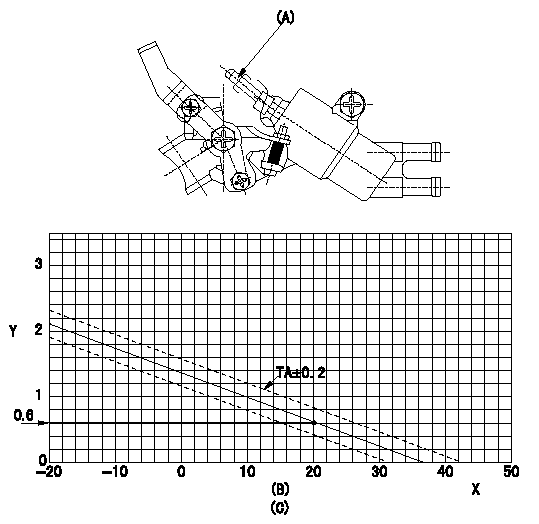
Adjustment of the W-CSD
1. Adjustment of the advance angle of the timer
(1)Determine the timer advance angle using the following graph.
(2)(1) Adjust with the screw (A) so that the timer advance angle determined in the item (1) is obtained.
X:Temperature t (deg C)
Y:Timer stroke TA (mm)
(B): Timer stroke TA (mm):
----------
----------
(C)=TA=-0.0376t+1.38(-20<=t)
----------
----------
(C)=TA=-0.0376t+1.38(-20<=t)
0000001901 W-FICD LEVER ADJUSTMENT
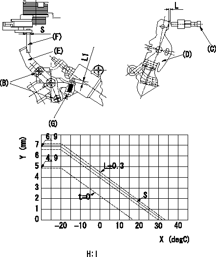
2. Adjustment of the W-FICD
(1)Insert a block gauge L2 determined from the graph below between the control lever (D) and the idling stopper bolt (C).
(2)Insert a shim S between the W-FICD lever (E) and the control lever (F). Adjust the W-FICD lever (E) so that it contacts the control lever (F) and fix it using bolt (B).
TT
Note:
a) The temperature of wax at the time of adjustment must not exceed a.
b) After completion of the adjustment, confirm that allowance for adjustment of the screw (G) is at least L1.
X:Temperature X (deg C)
Y:Control lever: dimension L (mm) (control lever position)
H:Graph, L - X graph
----------
L2=L+-0.05mm S=3+-0.05mm T=3.4~4.9N-m(0.35~0.5kgf-m) a=30degC L1=3mm
----------
L1=3++mm S=(3mm) H:L=-0.132X+4.29(-20<=X)(S=3+-0.05)
----------
L2=L+-0.05mm S=3+-0.05mm T=3.4~4.9N-m(0.35~0.5kgf-m) a=30degC L1=3mm
----------
L1=3++mm S=(3mm) H:L=-0.132X+4.29(-20<=X)(S=3+-0.05)
0000002001 V-FICD ADJUSTMENT
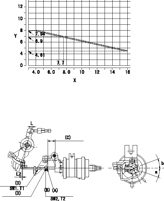
Adjustment of the two stage actuator (FICD).
(B): Stroke adjusting nut
(C): Actuator stroke
(D): Nut for adjusting the position of the rod
X:Injection quantity (cm3/1,000st)
Y:Thickness of the shim = L (mm)
1. Selecting the shim for adjusting the actuator.
(1)Measure the injection quantity at N by inserting the shim L1 between the control lever and the idling stopper bolt.
(2)Select the thickness (L) of the shim for adjusting the actuator using the following formula (Refer to the graph.).
Calculation: L+-0.1
2. Adjustment of the actuator
(1)Mount the actuator to the injection pump.
(2)Position the control lever at the idling position.
(3)Adjust with the nut (D) so that the space between the control lever and the rod becomes L2.
(4)Insert the shim (L) determined above between the control lever and the idling stopper bolt.
(5)Adjust the position of the screw (A) so that the actuator can make its full stroke (Reference value: L3 approx.) and fix with the nut (B).
(6)Standard for adjusting the position of the rod: allowable angle in the direction of the rotation: c
----------
N=900r/min L1=6.9mm L:L+-0.1=-0.2778Q+9.056(4.0<=Q<=16.0cm3/1,000st) L2=1+1mm L3=-mm c=+-20deg
----------
L2=1+1mm SW1=SW7 T1=1.4~2.0Nm{0.14~0.2kgfm} SW2=SW8 T2=3.5~5.0Nm{0.35~0.5kgfm} a=20deg b=20deg
----------
N=900r/min L1=6.9mm L:L+-0.1=-0.2778Q+9.056(4.0<=Q<=16.0cm3/1,000st) L2=1+1mm L3=-mm c=+-20deg
----------
L2=1+1mm SW1=SW7 T1=1.4~2.0Nm{0.14~0.2kgfm} SW2=SW8 T2=3.5~5.0Nm{0.35~0.5kgfm} a=20deg b=20deg
Information:
The information supplied in this service letter may not be valid after the termination date of this program. Do not perform the work outlined in this Service Letter after the termination date without first contacting your Caterpillar product analyst.
This Program can only be administered after a failure occurs. The decision whether to apply the Program is made by the dealer. When reporting the repair, use "PS5331" as the Part Number and "7755" as the Group Number. Use "96" as the Warranty Claim Description Code and use "Z" as the SIMS Description Code.
Termination Date
October 31, 1998Problem
Some 3116 and 3126 HEUI Engines may have excessive oil consumption as a result of oil leaking past the intensifier piston o-ring inside the injector. Engine oil consumption becomes excessive and may increase rapidly. There are no traditional signs of oil consumption, smoke, blow-by, etc. The engine has no performance problem, has good power and normal exhaust smoke.
The problem seems to be very low frequency and is not batch related.
Affected Product
Model & Identification Number
3116 (8WL1-Up)
3126 (1WM1-Up 4ES1-Up )
Parts Needed
3116 Engines6 - 1162784 Injectors (for 170 Hp)6 - 1166706 Injectors (for 185, 195, 215, 230, 250 and 275 Hp) 3126 Engines6 - 0R4970 Injectors (for 230, 250, 275, 300 and 330 Hp)6 - 0R4972 Injectors (for 175, 190 and 210 Hp)Action Required
See the attached rework procedure.
Service Claim Allowances
Labor Hour Breakdown TK = TopKickMC = Medium Hood ConventionalClaim 1290-500 for an additional 1.6 hours if the repair is made in a motor home chassis, cab type (RV), or bus chassis, cab type (BU).
Parts Disposition
TEPS/MEPS Dealers must return the affected part(s) to their Caterpillar dealer.
Parts must be returned undamaged in the original shipping boxes to:
Caterpillar Inc.
Attn: Michael Mosley - PS5331
8401 N. University
Peoria, Illinois 61615
Injectors must be sealed in a plastic bag to prevent fuel from leaking out during shipment.
A clear, legible copy of the service report in a plastic page protector must be included in the box with the returned injectors. The report must be packaged to arrive free of oil, grease and diesel fuel.
Attach.(1 - Rework Procedure)Rework Procedure
Check to see if PS8826 (Jumper-tube Rework) is to be applied to the affected engine. Perform PS8826 if it has not been performed prior to oil consumption test.
Document the oil consumption for 30 days using the attached Oil Consumption Test Sheet, Form Number 01-081227.
All of the following steps must be followed in order to establish base line data for oil consumption for full warranty reimbursement.
1. Change oil and filter at the beginning of the test to establish base line at normal change interval. Use CG-4 oil and new oil filter. Oil and filter are not claimable under this letter.
2. Refill with the proper amount of oil; 27liters/29 quarts, and 18 liters/19 quarts per the July 1997 Operations Maintenance Manual.3. Inspect for external leaks around the gaskets and the front and rear main seals.4. Inspect the air compressor air tanks for excess oil.5. Inspect the turbo oil drain line for excessive oil indicating seal leak.6. At the completion of
Have questions with 104745-8020?
Group cross 104745-8020 ZEXEL
Mitsubishi
Mitsubishi
104745-8020
9 460 610 959
MD325844
INJECTION-PUMP ASSEMBLY
4D56
4D56