Information injection-pump assembly
BOSCH
9 460 610 929
9460610929
ZEXEL
104745-3860
1047453860

Rating:
Components :
| 0. | INJECTION-PUMP ASSEMBLY | 104745-3860 |
| 1. | _ | |
| 2. | FUEL INJECTION PUMP | 104645-3860 |
| 3. | NUMBER PLATE | 146958-6800 |
| 4. | _ | 479771-0520 |
| 5. | CAPSULE | |
| 6. | ADJUSTING DEVICE | |
| 7. | NOZZLE AND HOLDER ASSY | 105148-1311 |
| 8. | Nozzle and Holder | MD196607 |
| 9. | Open Pre:MPa(Kqf/cm2) | 14.7{150} |
| 10. | NOZZLE-HOLDER | 105078-0181 |
| 11. | NOZZLE | 105007-1300 |
Scheme ###:
| 1/6. | [1] | 146601-0700 | PACKING RING |
| 6. | [1] | 146100-0220 | SUPPLY PUMP |
| 9. | [1] | 146103-0100 | COVER |
| 10. | [2] | 139104-0000 | FLAT-HEAD SCREW |
| 12. | [1] | 146200-0320 | DRIVE SHAFT |
| 12/1. | [1] | 146200-0300 | DRIVE SHAFT |
| 12/2. | [1] | 146201-0000 | WOODRUFF KEY |
| 12/3. | [2] | 146202-0100 | DAMPER |
| 12/4. | [1] | 146203-0000 | TOOTHED GEAR |
| 17. | [1] | 146204-0000 | PLAIN WASHER |
| 20. | [1] | 146210-3520 | ROLLER SET |
| 24. | [1] | 146303-0000 | BEARING PIN |
| 25. | [1] | 146304-0000 | BEARING PIN |
| 26. | [1] | 146305-0000 | CLAMPING BAND |
| 27. | [1] | 146205-0000 | SLOTTED WASHER |
| 29. | [1] | 146220-0020 | CAM PLATE |
| 30. | [1] | 146600-0800 | O-RING |
| 31. | [1] | 146311-6320 | PUMP PLUNGER |
| 32. | [1] | 146301-0000 | SLIDING PIECE |
| 34. | [1] | 146312-2900 | COMPRESSION SPRING |
| 34B. | [1] | 146312-2800 | COMPRESSION SPRING |
| 34C. | [1] | 146312-3200 | COMPRESSION SPRING |
| 35/1. | [1] | 146690-3200 | SHIM D11.5&9.4T0.1 |
| 35/1. | [1] | 146690-3300 | SHIM D11.5&9.4T0.2 |
| 35/1. | [1] | 146690-3400 | SHIM D11.5&9.4T0.25 |
| 35/1. | [1] | 146690-3500 | SHIM D11.5&9.4T1.0 |
| 35/1. | [1] | 146690-4100 | SHIM D11.5&9.4T2 |
| 35/1. | [1] | 146690-4200 | SHIM D11.5&9.4T0.5 |
| 35/1. | [1] | 146690-4300 | SHIM D11.5&9.4T0.75 |
| 36. | [1] | 146600-0800 | O-RING |
| 37. | [1] | 146310-1600 | COVER |
| 38. | [2] | 146620-5000 | BLEEDER SCREW |
| 39. | [1] | 146310-0100 | COVER |
| 40. | [2] | 146620-5000 | BLEEDER SCREW |
| 41. | [1] | 146312-1900 | COMPRESSION SPRING |
| 42. | [1] | 146602-8500 | PLAIN WASHER |
| 43. | [1] | 146230-0000 | SHIM |
| 44. | [1] | 146230-0100 | PLAIN WASHER |
| 45. | [1] | 146231-0001 | SLOTTED WASHER |
| 47. | [2] | 146233-0000 | SLOTTED WASHER |
| 48/1. | [1] | 146603-0000 | SHIM D17.0&5.2T0.50 |
| 48/1. | [1] | 146603-0100 | SHIM D17.0&5.2T0.80 |
| 48/1. | [1] | 146603-0200 | SHIM D17.0&5.2T1.00 |
| 48/1. | [1] | 146603-0300 | SHIM D17.0&5.2T1.20 |
| 48/1. | [1] | 146603-0400 | SHIM D17.0&5.2T1.50 |
| 48/1. | [1] | 146603-0500 | SHIM D17.0&5.2T1.80 |
| 48/1. | [1] | 146603-0600 | SHIM D17.0&5.2T2.00 |
| 48/1. | [1] | 146690-1400 | SHIM D17&5.2T0.9 |
| 48/1. | [1] | 146690-1500 | SHIM D17&5.2T1.1 |
| 48/1. | [1] | 146690-1600 | SHIM D17&5.2T1.3 |
| 48/1. | [1] | 146690-1700 | SHIM D17&5.2T1.4 |
| 48/1. | [1] | 146690-1800 | SHIM D17&5.2T1.6 |
| 48/1. | [1] | 146690-1900 | SHIM D17&5.2T1.7 |
| 48/1. | [1] | 146690-5800 | SHIM |
| 48/1. | [1] | 146690-5900 | SHIM |
| 48/1. | [1] | 146690-6000 | SHIM |
| 48/1. | [1] | 146690-6100 | SHIM |
| 48/1. | [1] | 146690-6200 | SHIM |
| 48/1. | [1] | 146690-6300 | SHIM |
| 48/1. | [1] | 146690-6400 | SHIM |
| 48/1. | [1] | 146690-6500 | SHIM |
| 48/1. | [1] | 146690-6600 | SHIM |
| 48/1. | [1] | 146690-6700 | SHIM |
| 48/1. | [1] | 146690-6800 | SHIM |
| 48/1. | [1] | 146690-6900 | SHIM |
| 48/1. | [1] | 146690-7000 | SHIM |
| 48/1. | [1] | 146690-7100 | SHIM |
| 48/1. | [1] | 146690-7200 | SHIM |
| 48/1. | [1] | 146690-7300 | SHIM |
| 48/1. | [1] | 146690-7400 | SHIM |
| 48/1. | [1] | 146690-7500 | SHIM |
| 48/1. | [1] | 146690-7800 | SHIM |
| 49. | [2] | 146234-0020 | GUIDE PIN |
| 50. | [1] | 146401-3220 | HYDRAULIC HEAD |
| 50. | [1] | 146401-3220 | HYDRAULIC HEAD |
| 51. | [1] | 146600-0000 | O-RING |
| 51. | [1] | 146600-0000 | O-RING |
| 52/1. | [1] | 146420-0000 | SHIM D9.5&3.0T1.90 |
| 52/1. | [1] | 146420-0100 | SHIM D9.5&3.0T1.92 |
| 52/1. | [1] | 146420-0200 | SHIM D9.5&3.0T1.94 |
| 52/1. | [1] | 146420-0300 | SHIM D9.5&3.0T1.96 |
| 52/1. | [1] | 146420-0400 | SHIM D9.5&3.0T1.98 |
| 52/1. | [1] | 146420-0500 | SHIM D9.5&3.0T2.00 |
| 52/1. | [1] | 146420-0600 | SHIM D9.5&3.0T2.02 |
| 52/1. | [1] | 146420-0700 | SHIM D9.5&3.0T2.04 |
| 52/1. | [1] | 146420-0800 | SHIM D9.5&3.0T2.06 |
| 52/1. | [1] | 146420-0900 | SHIM D9.5&3.0T2.08 |
| 52/1. | [1] | 146420-1000 | SHIM D9.5&3.0T2.10 |
| 52/1. | [1] | 146420-1100 | SHIM D9.5&3.0T2.12 |
| 52/1. | [1] | 146420-1200 | SHIM D9.5&3.0T2.14 |
| 52/1. | [1] | 146420-1300 | SHIM D9.5&3.0T2.16 |
| 52/1. | [1] | 146420-1400 | SHIM D9.5&3.0T2.18 |
| 52/1. | [1] | 146420-1500 | SHIM D9.5&3.0T2.20 |
| 52/1. | [1] | 146420-1600 | SHIM D9.5&3.0T2.22 |
| 52/1. | [1] | 146420-1700 | SHIM D9.5&3.0T2.24 |
| 52/1. | [1] | 146420-1800 | SHIM D9.5&3.0T2.26 |
| 52/1. | [1] | 146420-1900 | SHIM D9.5&3.0T2.28 |
| 52/1. | [1] | 146420-2000 | SHIM D9.5&3.0T2.30 |
| 52/1. | [1] | 146420-2100 | SHIM D9.5&3.0T2.32 |
| 52/1. | [1] | 146420-2200 | SHIM D9.5&3.0T2.34 |
| 52/1. | [1] | 146420-2300 | SHIM D9.5&3.0T2.36 |
| 52/1. | [1] | 146420-2400 | SHIM D9.5&3.0T2.38 |
| 52/1. | [1] | 146420-2500 | SHIM D9.5&3.0T2.40 |
| 52/1. | [1] | 146420-2600 | SHIM D9.5&3.0T2.42 |
| 52/1. | [1] | 146420-2700 | SHIM D9.5&3.0T2.44 |
| 52/1. | [1] | 146420-2800 | SHIM D9.5&3.0T2.46 |
| 52/1. | [1] | 146420-2900 | SHIM D9.5&3.0T2.48 |
| 52/1. | [1] | 146420-3000 | SHIM D9.5&3.0T2.50 |
| 52/1. | [1] | 146420-3100 | SHIM D9.5&3.0T2.52 |
| 52/1. | [1] | 146420-3200 | SHIM D9.5&3.0T2.54 |
| 52/1. | [1] | 146420-3300 | SHIM D9.5&3.0T2.56 |
| 52/1. | [1] | 146420-3400 | SHIM D9.5&3.0T2.58 |
| 52/1. | [1] | 146420-3500 | SHIM D9.5&3.0T2.60 |
| 52/1. | [1] | 146420-3600 | SHIM D9.5&3.0T2.62 |
| 52/1. | [1] | 146420-3700 | SHIM D9.5&3.0T2.64 |
| 52/1. | [1] | 146420-3800 | SHIM D9.5&3.0T2.66 |
| 52/1. | [1] | 146420-3900 | SHIM D9.5&3.0T2.68 |
| 52/1. | [1] | 146420-4000 | SHIM D9.5&3.0T2.70 |
| 52/1. | [1] | 146420-4100 | SHIM D9.5&3.0T2.72 |
| 52/1. | [1] | 146420-4200 | SHIM D9.5&3.0T2.74 |
| 52/1. | [1] | 146420-4300 | SHIM D9.5&3.0T2.76 |
| 52/1. | [1] | 146420-4400 | SHIM D9.5&3.0T2.78 |
| 52/1. | [1] | 146420-4500 | SHIM D9.5&3.0T2.80 |
| 52/1. | [1] | 146420-4600 | SHIM D9.5&3.0T2.82 |
| 52/1. | [1] | 146420-4700 | SHIM D9.5&3.0T2.84 |
| 52/1. | [1] | 146420-4800 | SHIM D9.5&3.0T2.86 |
| 52/1. | [1] | 146420-4900 | SHIM D9.5&3.0T2.88 |
| 52/1. | [1] | 146420-5000 | SHIM D9.5&3.0T2.90 |
| 52/1. | [1] | 146420-5100 | SHIM D9.5&3.0T1.74 |
| 52/1. | [1] | 146420-5200 | SHIM D9.5&3.0T1.76 |
| 52/1. | [1] | 146420-5300 | SHIM D9.5&3.0T1.78 |
| 52/1. | [1] | 146420-5400 | SHIM D9.5&3.0T1.80 |
| 52/1. | [1] | 146420-5500 | SHIM D9.5&3.0T1.82 |
| 52/1. | [1] | 146420-5600 | SHIM D9.5&3.0T1.84 |
| 52/1. | [1] | 146420-5700 | SHIM D9.5&3.0T1.86 |
| 52/1. | [1] | 146420-5800 | SHIM D9.5&3.0T1.88 |
| 54. | [4] | 146433-0100 | GASKET D12&6.4T1.00 |
| 55. | [4] | 146430-2020 | DELIVERY-VALVE ASSEMBLY |
| 56. | [4] | 146432-0000 | COMPRESSION SPRING |
| 58. | [4] | 146440-0320 | FITTING |
| 60. | [3] | 139106-0100 | FLAT-HEAD SCREW |
| 67. | [1] | 146701-4420 | MANIFOLD-PRESSURE COMP. |
| 67/1. | [1] | 146805-7220 | GOVERNOR COVER |
| 67/2. | [1] | 146515-0320 | CONTROL SHAFT |
| 67/3. | [1] | 146600-0100 | O-RING |
| 67/4. | [1] | 139310-0200 | PLAIN WASHER |
| 67/14. | [1] | 146621-1700 | UNION NUT |
| 67/16. | [1] | 146526-3000 | BLEEDER SCREW |
| 67/23. | [1] | 146925-7520 | BRACKET |
| 67/24. | [2] | 010206-2240 | HEX-SOCKET-HEAD CAP SCREW |
| 67/31. | [1] | 146710-0800 | BUSHING |
| 67/32. | [1] | 146711-0000 | PLATE |
| 67/33. | [1] | 139218-0400 | UNION NUT |
| 67/34. | [1] | 146712-0700 | BEARING PIN |
| 67/35. | [1] | 146621-0300 | UNION NUT |
| 67/36. | [1] | 146600-1400 | O-RING |
| 67/37. | [1] | 146710-0100 | BUSHING |
| 67/38. | [1] | 139506-0200 | GASKET D8.9&6.8T1.00 |
| 67/39. | [1] | 146620-0300 | CAPSULE |
| 67/40. | [1] | 026512-1540 | GASKET D15.4&12.2T1.50 |
| 67/41. | [1] | 146713-4100 | ADJUSTING PIN |
| 67/42. | [2] | 146714-0000 | PLATE |
| 67/43. | [1] | 146715-0000 | DIAPHRAGM |
| 67/44. | [1] | 139306-0100 | LOCKING WASHER |
| 67/45. | [1] | 013030-6040 | UNION NUT M6P1H3.6 |
| 67/46. | [1] | 146716-0000 | UNION NUT |
| 67/47. | [1] | 146717-0400 | COILED SPRING |
| 67/48/1. | [1] | 146720-0000 | SPACER BUSHING L3.7 |
| 67/48/1. | [1] | 146720-0100 | SPACER BUSHING L3.9 |
| 67/48/1. | [1] | 146720-0200 | SPACER BUSHING L4.1 |
| 67/48/1. | [1] | 146720-0300 | SPACER BUSHING L4.3 |
| 67/48/1. | [1] | 146720-0400 | SPACER BUSHING L4.5 |
| 67/48/1. | [1] | 146720-0500 | SPACER BUSHING L4.7 |
| 67/48/1. | [1] | 146720-0600 | SPACER BUSHING L4.9 |
| 67/48/1. | [1] | 146720-0700 | SPACER BUSHING L5.1 |
| 67/48/1. | [1] | 146720-0800 | SPACER BUSHING L5.3 |
| 67/48/1. | [1] | 146720-0900 | SPACER BUSHING L2.7 |
| 67/48/1. | [1] | 146720-1000 | SPACER BUSHING L2.9 |
| 67/48/1. | [1] | 146720-1100 | SPACER BUSHING L3.1 |
| 67/48/1. | [1] | 146720-1200 | SPACER BUSHING L3.3 |
| 67/48/1. | [1] | 146720-1300 | SPACER BUSHING L3.5 |
| 67/48/1. | [1] | 146720-1400 | SPACER BUSHING L2.8 |
| 67/48/1. | [1] | 146720-1500 | SPACER BUSHING L3.0 |
| 67/48/1. | [1] | 146720-1600 | SPACER BUSHING L3.2 |
| 67/48/1. | [1] | 146720-1700 | SPACER BUSHING L3.4 |
| 67/48/1. | [1] | 146720-1800 | SPACER BUSHING L3.6 |
| 67/48/1. | [1] | 146720-1900 | SPACER BUSHING L3.8 |
| 67/48/1. | [1] | 146720-2000 | SPACER BUSHING L4.0 |
| 67/48/1. | [1] | 146720-2100 | SPACER BUSHING L4.2 |
| 67/48/1. | [1] | 146720-2200 | SPACER BUSHING L4.4 |
| 67/48/1. | [1] | 146720-2300 | SPACER BUSHING L4.6 |
| 67/48/1. | [1] | 146720-2400 | SPACER BUSHING L4.8 |
| 67/48/1. | [1] | 146720-2500 | SPACER BUSHING L5.0 |
| 67/48/1. | [1] | 146720-2600 | SPACER BUSHING L5.2 |
| 67/48/1. | [1] | 146720-2700 | SPACER BUSHING L5.4 |
| 67/48/1. | [1] | 146720-2800 | SPACER BUSHING L5.5 |
| 67/48/1. | [1] | 146720-2900 | SPACER BUSHING L5.6 |
| 67/48/1. | [1] | 146720-4500 | SPACER BUSHING L1.8 |
| 67/48/1. | [1] | 146720-4600 | SPACER BUSHING L1.9 |
| 67/48/1. | [1] | 146720-4700 | SPACER BUSHING L2.0 |
| 67/48/1. | [1] | 146720-4800 | SPACER BUSHING L2.1 |
| 67/48/1. | [1] | 146720-4900 | SPACER BUSHING L2.2 |
| 67/48/1. | [1] | 146720-5000 | SPACER BUSHING L2.3 |
| 67/48/1. | [1] | 146720-5100 | SPACER BUSHING L2.4 |
| 67/48/1. | [1] | 146720-5200 | SPACER BUSHING L2.5 |
| 67/48/1. | [1] | 146720-5300 | SPACER BUSHING L2.6 |
| 67/48/1. | [1] | 146725-2500 | SPACER BUSHING L5.7 |
| 67/48/1. | [1] | 146725-2600 | SPACER BUSHING L5.8 |
| 67/48/1. | [1] | 146725-2700 | SPACER BUSHING L5.9 |
| 67/48/1. | [1] | 146725-2800 | SPACER BUSHING L6.0 |
| 67/48/1. | [1] | 146725-2900 | SPACER BUSHING L6.1 |
| 67/48/1. | [1] | 146725-3000 | SPACER BUSHING L6.2 |
| 67/48/1. | [1] | 146725-3100 | SPACER BUSHING L6.3 |
| 67/48/1. | [1] | 146725-3200 | SPACER BUSHING L6.4 |
| 67/48/1. | [1] | 146725-3300 | SPACER BUSHING L6.5 |
| 67/48/1. | [1] | 146725-3400 | SPACER BUSHING L6.6 |
| 67/48/1. | [1] | 146725-3500 | SPACER BUSHING L6.7 |
| 67/48/1. | [1] | 146725-3600 | SPACER BUSHING L6.8 |
| 67/48/1. | [1] | 146725-3700 | SPACER BUSHING L6.9 |
| 67/48/1. | [1] | 146725-3800 | SPACER BUSHING L7.0 |
| 67/48/1. | [1] | 146725-3900 | SPACER BUSHING L7.1 |
| 67/48/1. | [1] | 146725-4000 | SPACER BUSHING L7.2 |
| 67/48/1. | [1] | 146725-4100 | SPACER BUSHING L7.3 |
| 67/48/1. | [1] | 146725-4200 | SPACER BUSHING L7.4 |
| 67/48/1. | [1] | 146725-4300 | SPACER BUSHING L7.5 |
| 67/49. | [1] | 146721-3820 | COVER |
| 67/50. | [1] | 146722-0200 | FLAT-HEAD SCREW |
| 67/51. | [1] | 146600-0300 | O-RING |
| 67/53. | [1] | 013020-6040 | UNION NUT M6P1H5 |
| 67/54. | [2] | 139006-4700 | BLEEDER SCREW |
| 67/55. | [2] | 139006-4600 | BLEEDER SCREW |
| 67/56. | [1] | 146723-0200 | CONTROL LEVER |
| 67/57. | [1] | 146712-0100 | BEARING PIN |
| 67/58. | [2] | 146620-0600 | CAPSULE |
| 67/59. | [2] | 026506-1040 | GASKET D9.9&6.2T1 |
| 67/60. | [1] | 146724-0300 | ELEMENT |
| 67/61. | [1] | 146724-0600 | CAPSULE |
| 67/78. | [1] | 146600-4400 | SEAL RING |
| 67/96. | [1] | 146659-6320 | CLAMPING BAND |
| 67/102. | [1] | 146932-6822 | BRACKET |
| 67/109. | [1] | 146649-2200 | SPACER BUSHING |
| 67/112. | [1] | 146926-5520 | BRACKET |
| 67/200. | [1] | 139308-0300 | PLAIN WASHER |
| 67/201. | [1] | 146545-3400 | THREADED PIN L53.00 |
| 67/201B. | [1] | 146545-3500 | THREADED PIN L55.00 |
| 67/201C. | [1] | 146545-3600 | THREADED PIN L57.00 |
| 67/202. | [1] | 139208-0900 | UNION NUT |
| 67/203. | [1] | 146600-1200 | O-RING |
| 72. | [1] | 146830-7120 | CONTROL LEVER |
| 72B. | [1] | 146830-7220 | CONTROL LEVER |
| 73. | [1] | 014110-6440 | LOCKING WASHER |
| 75. | [1] | 013020-6040 | UNION NUT M6P1H5 |
| 95. | [1] | 146550-1620 | FULCRUM LEVER |
| 104. | [2] | 146568-0000 | SLOTTED SPRING PIN |
| 105. | [2] | 026508-1140 | GASKET D11.4&8.2T1 |
| 106. | [2] | 146588-0500 | COILED SPRING |
| 107. | [1] | 146569-0300 | UNION NUT |
| 108. | [1] | 146570-0420 | GOVERNOR SHAFT |
| 109. | [1] | 146600-0400 | O-RING |
| 110/1. | [1] | 146571-0000 | SHIM D20.2&8.3T1.05 |
| 110/1. | [1] | 146571-0100 | SHIM D20.2&8.3T1.25 |
| 110/1. | [1] | 146571-0200 | SHIM D20.2&8.3T1.45 |
| 110/1. | [1] | 146571-0300 | SHIM D20.2&8.3T1.65 |
| 110/1. | [1] | 146571-0400 | SHIM D20.2&8.3T1.85 |
| 110/1. | [1] | 146571-0500 | SHIM D20.2&8.3T1.15 |
| 110/1. | [1] | 146571-0600 | SHIM D20.2&8.3T1.35 |
| 110/1. | [1] | 146571-0700 | SHIM D20.2&8.3T1.55 |
| 110/1. | [1] | 146571-0800 | SHIM D20.2&8.3T1.75 |
| 111. | [1] | 146602-0600 | PLAIN WASHER D20&8.4T1.40 |
| 112. | [1] | 146572-0020 | FLYWEIGHT ASSEMBLY |
| 114. | [1] | 146602-0500 | PLAIN WASHER D17&6.4T1.60 |
| 115. | [1] | 146875-8300 | SLIDING SLEEVE |
| 116. | [1] | 146576-0000 | SEALING CAP |
| 117/1. | [1] | 146577-1800 | PLUG L2.10 |
| 117/1. | [1] | 146577-1900 | PLUG L2.30 |
| 117/1. | [1] | 146577-2000 | PLUG L2.50 |
| 117/1. | [1] | 146577-2100 | PLUG L2.70 |
| 117/1. | [1] | 146577-2200 | PLUG L2.90 |
| 117/1. | [1] | 146577-2300 | PLUG L3.10 |
| 117/1. | [1] | 146577-2400 | PLUG L3.30 |
| 117/1. | [1] | 146577-2500 | PLUG L3.50 |
| 117/1. | [1] | 146577-2600 | PLUG L3.70 |
| 117/1. | [1] | 146577-2700 | PLUG L3.90 |
| 117/1. | [1] | 146577-2800 | PLUG L4.10 |
| 117/1. | [1] | 146577-2900 | PLUG L4.30 |
| 117/1. | [1] | 146577-3000 | PLUG L4.50 |
| 117/1. | [1] | 146577-3100 | PLUG L4.70 |
| 117/1. | [1] | 146577-3200 | PLUG L4.90 |
| 117/1. | [1] | 146577-3300 | PLUG L5.10 |
| 117/1. | [1] | 146577-6700 | PLUG L2.2 |
| 117/1. | [1] | 146577-6800 | PLUG L2.4 |
| 117/1. | [1] | 146577-6900 | PLUG L2.6 |
| 117/1. | [1] | 146577-7000 | PLUG L2.8 |
| 117/1. | [1] | 146577-7100 | PLUG L3.0 |
| 117/1. | [1] | 146577-7200 | PLUG L3.2 |
| 117/1. | [1] | 146577-7300 | PLUG L3.4 |
| 117/1. | [1] | 146577-7400 | PLUG L3.6 |
| 117/1. | [1] | 146577-7500 | PLUG L3.8 |
| 117/1. | [1] | 146577-7600 | PLUG L4.0 |
| 117/1. | [1] | 146577-7700 | PLUG L4.2 |
| 117/1. | [1] | 146577-7800 | PLUG L4.4 |
| 117/1. | [1] | 146577-7900 | PLUG L4.6 |
| 117/1. | [1] | 146577-8000 | PLUG L4.8 |
| 117/1. | [1] | 146577-8100 | PLUG L5.0 |
| 117/1. | [1] | 146877-0000 | PLUG L5.2 |
| 117/1. | [1] | 146877-0100 | PLUG L5.3 |
| 117/1. | [1] | 146877-0200 | PLUG L5.4 |
| 117/1. | [1] | 146877-0300 | PLUG L5.5 |
| 117/1. | [1] | 146877-4700 | PLUG |
| 117/1. | [1] | 146877-4800 | PLUG |
| 117/1. | [1] | 146877-4900 | PLUG |
| 117/1. | [1] | 146877-5000 | PLUG |
| 120. | [1] | 146879-0220 | RETAINING PIN |
| 122. | [1] | 146580-2300 | GOVERNOR SPRING |
| 123. | [4] | 146620-0500 | HEX-SOCKET-HEAD CAP SCREW |
| 130. | [1] | 146421-0020 | CAPSULE |
| 130/2. | [1] | 026508-1140 | GASKET D11.4&8.2T1 |
| 130/3. | [1] | 146422-0000 | BLEEDER SCREW |
| 130/4. | [1] | 146600-0500 | O-RING |
| 133. | [1] | 146600-0600 | O-RING |
| 134. | [1] | 146600-0700 | O-RING |
| 135. | [1] | 146110-0220 | CONTROL VALVE |
| 135/5. | [1] | 146114-0000 | SPRING WASHER |
| 136. | [1] | 146120-0020 | OVER FLOW VALVE |
| 137. | [2] | 026512-1840 | GASKET D17.9&12.2T1.50 |
| 138. | [1] | 146666-7220 | INLET UNION |
| 200. | [1] | 146206-0100 | COILED SPRING |
| 205. | [1] | 029470-4030 | WOODRUFF KEY |
| 217. | [1] | 146542-5300 | SLOTTED WASHER |
| 218. | [1] | 146592-2500 | COILED SPRING |
| 219. | [1] | 146541-3000 | BUSHING |
| 220. | [1] | 146592-2600 | COILED SPRING |
| 224. | [1] | 139006-4400 | BLEEDER SCREW |
| 230. | [1] | 146613-2500 | BRACKET |
| 231. | [1] | 139006-4400 | BLEEDER SCREW |
| 232. | [1] | 146931-3200 | BRACKET |
| 234. | [1] | 139006-4800 | BLEEDER SCREW |
| 235. | [1] | 146931-6100 | BRACKET |
| 237. | [1] | 146620-0200 | HEX-SOCKET-HEAD CAP SCREW |
| 240. | [1] | 146688-0120 | PULLING ELECTROMAGNET |
| 240/8. | [1] | 146600-1700 | O-RING |
| 242. | [1] | 407911-1410 | CONTROL UNIT |
| 243. | [1] | 146621-4900 | UNION NUT |
| 245. | [3] | 026512-1840 | GASKET D17.9&12.2T1.50 |
| 246. | [1] | 139812-1900 | EYE BOLT |
| 247. | [1] | 146666-7420 | INLET UNION |
| 248. | [1] | 146614-0200 | SPACER BUSHING |
| 251. | [1] | 146125-0101 | FILTER |
| 252. | [1] | 146125-0200 | COILED SPRING |
| 275. | [1] | 146612-4800 | BRACKET |
| 276. | [2] | 010010-1640 | BLEEDER SCREW M10P1.5L16 4T |
| 280. | [1] | 146361-3420 | START ADVANCE ASSY |
| 281. | [1] | 146600-0800 | O-RING |
| 360. | [1] | 146649-8800 | BUSHING |
| 361. | [1] | 146649-8900 | CAP |
| 362. | [2] | 146620-8402 | BLEEDER SCREW |
| 800S. | [1] | 146018-4820 | PUMP HOUSING |
| 800S/1/6. | [1] | 146601-0700 | PACKING RING |
| 804S. | [1] | 146232-0320 | COMPRESSION SPRING |
| 805S. | [1] | 146574-0120 | PARTS SET |
| 810S. | [1] | 146600-1120 | REPAIR SET |
| 835S. | [1] | 146598-1000 | CAP |
| 836S/1. | [1] | 146598-0600 | CAP L18 |
| 836S/1. | [1] | 146598-0700 | CAP L21 |
| 836S/1. | [1] | 146598-0800 | CAP L24 |
| 836S/1. | [1] | 146598-0900 | CAP L27 |
| 903. | [1] | 146672-2820 | PULSE GENERATOR |
| 903/2. | [1] | 146600-1300 | O-RING &13W1.9 |
| 906. | [1] | 146958-6800 | NAMEPLATE |
| 910S. | [1] | 146600-4220 | PARTS SET |
| 910S. | [1] | 146600-4220 | PARTS SET |
| 911S. | [1] | 146672-2820 | PULSE GENERATOR |
| 911S/2. | [1] | 146600-1300 | O-RING &13W1.9 |
| 912S. | [1] | 026508-1140 | GASKET D11.4&8.2T1 |
| 913S. | [1] | 146422-0000 | BLEEDER SCREW |
| 914S. | [1] | 146699-0620 | VALVE SET |
| 914S. | [1] | 146699-0620 | VALVE SET |
| 914S. | [1] | 146699-0620 | VALVE SET |
| 916S. | [1] | 025804-1610 | WOODRUFF KEY |
Include in #2:
104745-3860
as INJECTION-PUMP ASSEMBLY
Cross reference number
BOSCH
9 460 610 929
9460610929
ZEXEL
104745-3860
1047453860
Zexel num
Bosch num
Firm num
Name
Calibration Data:
Adjustment conditions
Test oil
1404 Test oil ISO4113orSAEJ967d
1404 Test oil ISO4113orSAEJ967d
Test oil temperature
degC
45
45
50
Nozzle
105780-0060
Bosch type code
NP-DN0SD1510
Nozzle holder
105780-2150
Opening pressure
MPa
13
13
13.3
Opening pressure
kgf/cm2
133
133
136
Injection pipe
157805-7320
Injection pipe
Inside diameter - outside diameter - length (mm) mm 2-6-450
Inside diameter - outside diameter - length (mm) mm 2-6-450
Joint assembly
157641-4720
Tube assembly
157641-4020
Transfer pump pressure
kPa
20
20
20
Transfer pump pressure
kgf/cm2
0.2
0.2
0.2
Direction of rotation (viewed from drive side)
Right R
Right R
Injection timing adjustment
Pump speed
r/min
750
750
750
Boost pressure
kPa
0
0
0
Boost pressure
mmHg
0
0
0
Average injection quantity
mm3/st.
50.6
50.1
51.1
Difference in delivery
mm3/st.
4
Basic
*
Oil temperature
degC
50
48
52
Remarks
NA
NA
Injection timing adjustment_02
Pump speed
r/min
750
750
750
Boost pressure
kPa
33.3
32
34.6
Boost pressure
mmHg
250
240
260
Average injection quantity
mm3/st.
57
56.5
57.5
Difference in delivery
mm3/st.
4.5
Basic
*
Oil temperature
degC
50
48
52
Remarks
CBS
CBS
Injection timing adjustment_03
Pump speed
r/min
1250
1250
1250
Boost pressure
kPa
73.3
72
74.6
Boost pressure
mmHg
550
540
560
Average injection quantity
mm3/st.
65.9
65.4
66.4
Difference in delivery
mm3/st.
5.5
Basic
*
Oil temperature
degC
50
48
52
Remarks
Full
Full
Injection timing adjustment_04
Pump speed
r/min
750
750
750
Boost pressure
kPa
0
0
0
Boost pressure
mmHg
0
0
0
Average injection quantity
mm3/st.
50.6
49.6
51.6
Oil temperature
degC
50
48
52
Injection timing adjustment_05
Pump speed
r/min
750
750
750
Boost pressure
kPa
33.3
32
34.6
Boost pressure
mmHg
250
240
260
Average injection quantity
mm3/st.
57
56
58
Basic
*
Oil temperature
degC
50
48
52
Remarks
CBS
CBS
Injection timing adjustment_06
Pump speed
r/min
1000
1000
1000
Boost pressure
kPa
73.3
72
74.6
Boost pressure
mmHg
550
540
560
Average injection quantity
mm3/st.
65.7
63.2
68.2
Oil temperature
degC
50
48
52
Injection timing adjustment_07
Pump speed
r/min
1250
1250
1250
Boost pressure
kPa
73.3
72
74.6
Boost pressure
mmHg
550
540
560
Average injection quantity
mm3/st.
65.9
64.9
66.9
Difference in delivery
mm3/st.
6
Basic
*
Oil temperature
degC
50
48
52
Remarks
Full
Full
Injection timing adjustment_08
Pump speed
r/min
1750
1750
1750
Boost pressure
kPa
73.3
72
74.6
Boost pressure
mmHg
550
540
560
Average injection quantity
mm3/st.
60
57.5
62.5
Oil temperature
degC
50
48
52
Injection timing adjustment_09
Pump speed
r/min
2100
2100
2100
Boost pressure
kPa
73.3
72
74.6
Boost pressure
mmHg
550
540
560
Average injection quantity
mm3/st.
53.7
51.2
56.2
Oil temperature
degC
52
50
54
Injection quantity adjustment
Pump speed
r/min
2650
2650
2650
Boost pressure
kPa
73.3
72
74.6
Boost pressure
mmHg
550
540
560
Average injection quantity
mm3/st.
27.9
24.9
30.9
Difference in delivery
mm3/st.
8.5
Basic
*
Oil temperature
degC
55
52
58
Injection quantity adjustment_02
Pump speed
r/min
3050
3050
3050
Boost pressure
kPa
73.3
72
74.6
Boost pressure
mmHg
550
540
560
Average injection quantity
mm3/st.
5
Oil temperature
degC
55
52
58
Injection quantity adjustment_03
Pump speed
r/min
2650
2650
2650
Boost pressure
kPa
73.3
72
74.6
Boost pressure
mmHg
550
540
560
Average injection quantity
mm3/st.
27.9
22.9
32.9
Difference in delivery
mm3/st.
9
Basic
*
Oil temperature
degC
55
52
58
Governor adjustment
Pump speed
r/min
375
375
375
Boost pressure
kPa
0
0
0
Boost pressure
mmHg
0
0
0
Average injection quantity
mm3/st.
16.4
14.9
17.9
Difference in delivery
mm3/st.
2
Basic
*
Oil temperature
degC
48
46
50
Governor adjustment_02
Pump speed
r/min
375
375
375
Boost pressure
kPa
0
0
0
Boost pressure
mmHg
0
0
0
Average injection quantity
mm3/st.
16.4
14.4
18.4
Difference in delivery
mm3/st.
2.5
Basic
*
Oil temperature
degC
48
46
50
Governor adjustment_03
Pump speed
r/min
750
750
750
Boost pressure
kPa
0
0
0
Boost pressure
mmHg
0
0
0
Average injection quantity
mm3/st.
5
Oil temperature
degC
50
48
52
Timer adjustment
Pump speed
r/min
100
100
100
Boost pressure
kPa
0
0
0
Boost pressure
mmHg
0
0
0
Average injection quantity
mm3/st.
75
65
85
Basic
*
Oil temperature
degC
48
46
50
Remarks
IDLE
IDLE
Timer adjustment_02
Pump speed
r/min
100
100
100
Boost pressure
kPa
0
0
0
Boost pressure
mmHg
0
0
0
Average injection quantity
mm3/st.
75
65
85
Oil temperature
degC
48
46
50
Remarks
IDLE
IDLE
Speed control lever angle
Pump speed
r/min
375
375
375
Boost pressure
kPa
0
0
0
Boost pressure
mmHg
0
0
0
Average injection quantity
mm3/st.
0
0
0
Oil temperature
degC
48
46
50
Remarks
Magnet OFF at idling position
Magnet OFF at idling position
0000000901
Pump speed
r/min
1250
1250
1250
Boost pressure
kPa
73.3
72
74.6
Boost pressure
mmHg
550
540
560
Overflow quantity
cm3/min
420
290
550
Oil temperature
degC
50
48
52
Stop lever angle
Pump speed
r/min
1250
1250
1250
Boost pressure
kPa
73.3
72
74.6
Boost pressure
mmHg
550
540
560
Pressure
kPa
549
520
578
Pressure
kgf/cm2
5.6
5.3
5.9
Basic
*
Oil temperature
degC
50
48
52
0000001101
Pump speed
r/min
1250
1250
1250
Boost pressure
kPa
73.3
72
74.6
Boost pressure
mmHg
550
540
560
Timer stroke
mm
4.6
4.4
4.8
Basic
*
Oil temperature
degC
50
48
52
_02
Pump speed
r/min
500
500
500
Boost pressure
kPa
73.3
72
74.6
Boost pressure
mmHg
550
540
560
Timer stroke
mm
1.2
0.6
1.8
Oil temperature
degC
48
46
50
_03
Pump speed
r/min
1000
1000
1000
Boost pressure
kPa
73.3
72
74.6
Boost pressure
mmHg
550
540
560
Timer stroke
mm
3.5
2.9
4.1
Oil temperature
degC
50
48
52
_04
Pump speed
r/min
1250
1250
1250
Boost pressure
kPa
73.3
72
74.6
Boost pressure
mmHg
550
540
560
Timer stroke
mm
4.6
4.2
5
Basic
*
Oil temperature
degC
50
48
52
_05
Pump speed
r/min
1500
1500
1500
Boost pressure
kPa
73.3
72
74.6
Boost pressure
mmHg
550
540
560
Timer stroke
mm
5.6
5
6.2
Oil temperature
degC
50
48
52
_06
Pump speed
r/min
2100
2100
2100
Boost pressure
kPa
73.3
72
74.6
Boost pressure
mmHg
550
540
560
Timer stroke
mm
7.8
7.2
8.4
Oil temperature
degC
52
50
54
0000001201
Max. applied voltage
V
8
8
8
Test voltage
V
13
12
14
0000001401
Pump speed
r/min
1250
1250
1250
Boost pressure
kPa
73.3
72
74.6
Boost pressure
mmHg
550
540
560
Average injection quantity
mm3/st.
56.9
56.4
57.4
Timer stroke TA
mm
3.9
3.7
4.1
Timer stroke variation dT
mm
0.7
0.7
0.7
Basic
*
Oil temperature
degC
50
48
52
_02
Pump speed
r/min
1250
1250
1250
Boost pressure
kPa
73.3
72
74.6
Boost pressure
mmHg
550
540
560
Average injection quantity
mm3/st.
56.9
55.9
57.9
Timer stroke TA
mm
3.9
3.5
4.3
Basic
*
Oil temperature
degC
50
48
52
_03
Pump speed
r/min
1250
1250
1250
Boost pressure
kPa
73.3
72
74.6
Boost pressure
mmHg
550
540
560
Average injection quantity
mm3/st.
43
42
44
Timer stroke TA
mm
2.5
1.9
3.1
Oil temperature
degC
50
48
52
Timing setting
K dimension
mm
3.3
3.2
3.4
KF dimension
mm
5.8
5.7
5.9
MS dimension
mm
1.4
1.3
1.5
Control lever angle alpha
deg.
61
57
65
Control lever angle beta
deg.
41
36
46
Test data Ex:
0000001801 W-CSD ADJUSTMENT
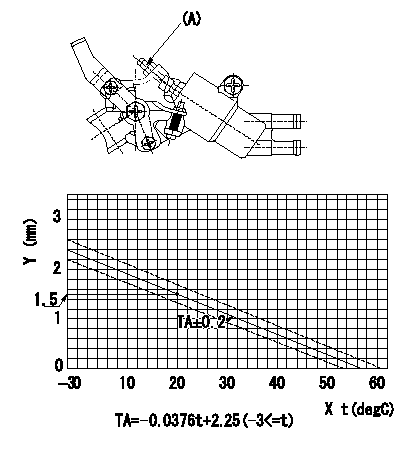
Adjustment of the W-CSD
1. Adjustment of the advance angle of the timer
(1)Determine the timer advance angle using the graph.
(2)(1) Adjust with the screw (A) so that the timer advance angle determined in the item (1) is obtained.
X = temperature t
Y = timer stroke
----------
----------
----------
----------
0000001901 W-FICD LEVER ADJUSTMENT
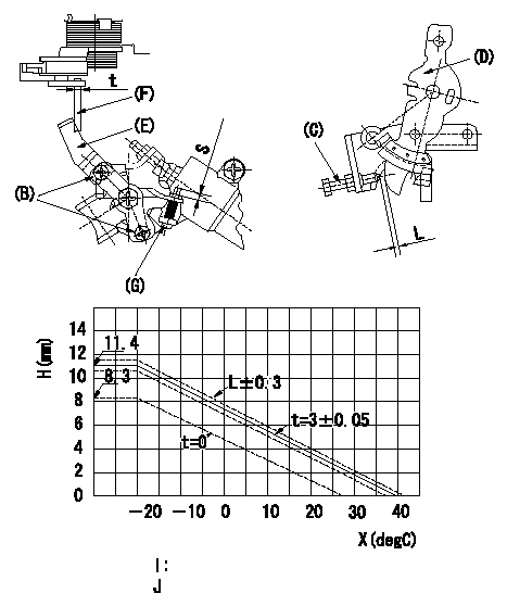
2. Adjustment of the W-FICD
(1)Insert a block gauge L1 determined from the graph below between the control lever (D) and the idling stopper bolt (C).
(2)Insert a shim t between the W-FICD lever (E) and the control lever (F). Adjust the W-FICD lever (E) so that it contacts the control lever (F) and fix it using bolt (B).
TT
Note:
a) The temperature of the wax at the time of adjustment must not exceed d.
b) After completing adjustment, confirm that adjustment allowance of the screw (G) is at least S.
H = control lever dimension L (control lever position)
X = temperature X
I = graph L - X
----------
L1=L+-0.05mm t=3+-0.05mm T=3.4~4.9N-m(0.35~0.5kgf-m) d=30degC S=3mm
----------
t=3mm S=Above 3mm J:L=-0.177X+7.80(-20<=X(degC))(t=3+-0.05)
----------
L1=L+-0.05mm t=3+-0.05mm T=3.4~4.9N-m(0.35~0.5kgf-m) d=30degC S=3mm
----------
t=3mm S=Above 3mm J:L=-0.177X+7.80(-20<=X(degC))(t=3+-0.05)
Information:
To many, the diesel principle may not be new, however, the special features of Caterpillar Diesel Truck Engines require that the operator and the maintenance personnel become acquainted with the systems in order to give the engine the best possible care. Maximum engine life depends a great deal on a good maintenance schedule performed by reliable personnel with a basic understanding of the working principles and systems.Diesel Engine Principle
This diesel engine operates on the reciprocating piston 4-stroke cycle, compression ignition principle, and burns fuels commercially known as diesel fuels. The basic differences between the spark ignition engine and the diesel engine are; the method of introducing fuel into the system and the method by which the fuel is ignited.The engine always takes a full charge of air into a cylinder on each inlet stroke, compresses it in an extremely small space causing the air to reach temperatures over 1000°F (537°C.). Fuel is injected into the cylinder as the piston nears the top of the compression stroke, where it mixes with the compressed air, and immediately starts to burn. This is called self-ignition, or spontaneous ignition. The expansion of the burning gases forces the piston down on a power stroke. Four Stroke Cycle Principle
The four stroke cycle engine has separate strokes for each basic function. The four strokes and the order in which they occur are: Intake, compression, power and exhaust.It must be remembered that for the four stroke cycle to function the inlet valves, exhaust valves and fuel injection must be timed in proper sequence with the piston. This is accomplished by timing gears between the crankshaft, the valve train and injection pumps. Intake Stroke: As the piston moves down on the inlet stroke, the inlet valve is opened and exhaust valve is closed by the camshaft and rocker arm arrangement. Air is drawn in through the air cleaner and intake valve by the partial vacuum caused by the piston traveling downward. Compression Stroke: At the end of the intake stroke the inlet valve closes and the exhaust valve remains closed. As the piston moves up, the air is compressed into an extremely small space causing the air temperature to rise high enough to ignite fuel. As the piston reaches near the top of the stroke, a measured amount of fuel is injected into the cylinder where it mixes with the compressed air and ignition begins. The atomized and burning fuel then rushes throughout the cylinder above the piston for complete combustion. Power Stroke: The piston is forced down by the pressure of the expanding and burning gases in the cylinder above the piston. During this power stroke, the intake and exhaust valves are closed. Exhaust Stroke: When the piston reaches the bottom of the power stroke the cylinder is filled with burned gases which must be expelled. As the piston begins its upward travel on the exhaust stroke, the exhaust valve is opened by the exhaust lobe on the cam. As the piston moves up, it forces