Information injection-pump assembly
BOSCH
9 460 610 741
9460610741
ZEXEL
104745-3831
1047453831
MITSUBISHI
MD323062
md323062

Rating:
Components :
| 0. | INJECTION-PUMP ASSEMBLY | 104745-3831 |
| 1. | _ | |
| 2. | FUEL INJECTION PUMP | 104645-3831 |
| 3. | NUMBER PLATE | 146970-0900 |
| 4. | _ | 146672-2820 |
| 5. | CAPSULE | |
| 6. | ADJUSTING DEVICE | |
| 7. | NOZZLE AND HOLDER ASSY | 105148-1311 |
| 8. | Nozzle and Holder | MD196607 |
| 9. | Open Pre:MPa(Kqf/cm2) | 14.7{150} |
| 10. | NOZZLE-HOLDER | 105078-0181 |
| 11. | NOZZLE | 105007-1300 |
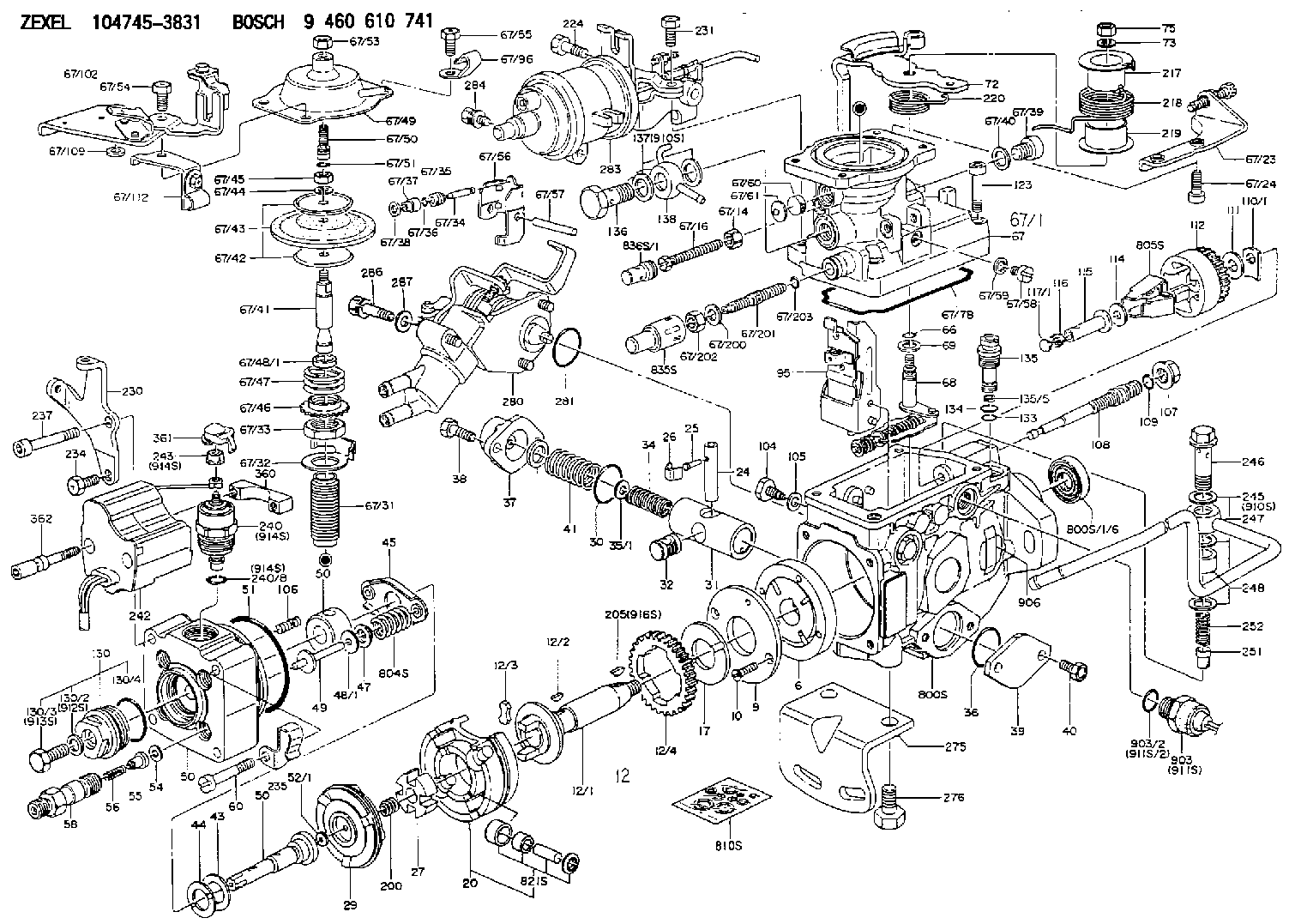
Scheme ###:
| 1/6. | [1] | 146601-0700 | PACKING RING |
| 6. | [1] | 146100-0220 | SUPPLY PUMP |
| 9. | [1] | 146103-0100 | COVER |
| 10. | [2] | 139104-0000 | FLAT-HEAD SCREW |
| 12. | [1] | 146200-0320 | DRIVE SHAFT |
| 12/1. | [1] | 146200-0300 | DRIVE SHAFT |
| 12/2. | [1] | 146201-0000 | WOODRUFF KEY |
| 12/3. | [2] | 146202-0100 | DAMPER |
| 12/4. | [1] | 146203-0000 | TOOTHED GEAR |
| 17. | [1] | 146204-0000 | PLAIN WASHER |
| 20. | [1] | 146210-3520 | ROLLER SET |
| 24. | [1] | 146303-0100 | BEARING PIN |
| 25. | [1] | 146304-0000 | BEARING PIN |
| 26. | [1] | 146305-0000 | CLAMPING BAND |
| 27. | [1] | 146205-0000 | SLOTTED WASHER |
| 29. | [1] | 146220-2120 | CAM PLATE |
| 30. | [1] | 146600-0800 | O-RING |
| 31. | [1] | 146311-6320 | PUMP PLUNGER |
| 32. | [1] | 146301-0000 | SLIDING PIECE |
| 34. | [1] | 146312-2900 | COMPRESSION SPRING |
| 34B. | [1] | 146312-2800 | COMPRESSION SPRING |
| 34C. | [1] | 146312-3200 | COMPRESSION SPRING |
| 35/1. | [1] | 146690-3200 | SHIM D11.5&9.4T0.1 |
| 35/1. | [1] | 146690-3300 | SHIM D11.5&9.4T0.2 |
| 35/1. | [1] | 146690-3400 | SHIM D11.5&9.4T0.25 |
| 35/1. | [1] | 146690-3500 | SHIM D11.5&9.4T1.0 |
| 35/1. | [1] | 146690-4100 | SHIM D11.5&9.4T2 |
| 35/1. | [1] | 146690-4200 | SHIM D11.5&9.4T0.5 |
| 35/1. | [1] | 146690-4300 | SHIM D11.5&9.4T0.75 |
| 36. | [1] | 146600-0800 | O-RING |
| 37. | [1] | 146310-4020 | COVER |
| 38. | [2] | 146620-5000 | BLEEDER SCREW |
| 39. | [1] | 146310-0100 | COVER |
| 40. | [2] | 146620-5000 | BLEEDER SCREW |
| 41. | [1] | 146312-1900 | COMPRESSION SPRING |
| 43. | [1] | 146230-0000 | SHIM |
| 44. | [1] | 146230-0100 | PLAIN WASHER |
| 45. | [1] | 146231-0001 | SLOTTED WASHER |
| 47. | [2] | 146233-0000 | SLOTTED WASHER |
| 48/1. | [1] | 146603-0000 | SHIM D17.0&5.2T0.50 |
| 48/1. | [1] | 146603-0100 | SHIM D17.0&5.2T0.80 |
| 48/1. | [1] | 146603-0200 | SHIM D17.0&5.2T1.00 |
| 48/1. | [1] | 146603-0300 | SHIM D17.0&5.2T1.20 |
| 48/1. | [1] | 146603-0400 | SHIM D17.0&5.2T1.50 |
| 48/1. | [1] | 146603-0500 | SHIM D17.0&5.2T1.80 |
| 48/1. | [1] | 146603-0600 | SHIM D17.0&5.2T2.00 |
| 48/1. | [1] | 146690-1400 | SHIM D17&5.2T0.9 |
| 48/1. | [1] | 146690-1500 | SHIM D17&5.2T1.1 |
| 48/1. | [1] | 146690-1600 | SHIM D17&5.2T1.3 |
| 48/1. | [1] | 146690-1700 | SHIM D17&5.2T1.4 |
| 48/1. | [1] | 146690-1800 | SHIM D17&5.2T1.6 |
| 48/1. | [1] | 146690-1900 | SHIM D17&5.2T1.7 |
| 48/1. | [1] | 146690-5800 | SHIM |
| 48/1. | [1] | 146690-5900 | SHIM |
| 48/1. | [1] | 146690-6000 | SHIM |
| 48/1. | [1] | 146690-6100 | SHIM |
| 48/1. | [1] | 146690-6200 | SHIM |
| 48/1. | [1] | 146690-6300 | SHIM |
| 48/1. | [1] | 146690-6400 | SHIM |
| 48/1. | [1] | 146690-6500 | SHIM |
| 48/1. | [1] | 146690-6600 | SHIM |
| 48/1. | [1] | 146690-6700 | SHIM |
| 48/1. | [1] | 146690-6800 | SHIM |
| 48/1. | [1] | 146690-6900 | SHIM |
| 48/1. | [1] | 146690-7000 | SHIM |
| 48/1. | [1] | 146690-7100 | SHIM |
| 48/1. | [1] | 146690-7200 | SHIM |
| 48/1. | [1] | 146690-7300 | SHIM |
| 48/1. | [1] | 146690-7400 | SHIM |
| 48/1. | [1] | 146690-7500 | SHIM |
| 48/1. | [1] | 146690-7800 | SHIM |
| 49. | [2] | 146234-0020 | GUIDE PIN |
| 50. | [1] | 146401-3320 | HYDRAULIC HEAD |
| 50. | [1] | 146401-3320 | HYDRAULIC HEAD |
| 50. | [1] | 146401-3320 | HYDRAULIC HEAD |
| 51. | [1] | 146600-0000 | O-RING |
| 52/1. | [1] | 146420-0000 | SHIM D9.5&3.0T1.90 |
| 52/1. | [1] | 146420-0100 | SHIM D9.5&3.0T1.92 |
| 52/1. | [1] | 146420-0200 | SHIM D9.5&3.0T1.94 |
| 52/1. | [1] | 146420-0300 | SHIM D9.5&3.0T1.96 |
| 52/1. | [1] | 146420-0400 | SHIM D9.5&3.0T1.98 |
| 52/1. | [1] | 146420-0500 | SHIM D9.5&3.0T2.00 |
| 52/1. | [1] | 146420-0600 | SHIM D9.5&3.0T2.02 |
| 52/1. | [1] | 146420-0700 | SHIM D9.5&3.0T2.04 |
| 52/1. | [1] | 146420-0800 | SHIM D9.5&3.0T2.06 |
| 52/1. | [1] | 146420-0900 | SHIM D9.5&3.0T2.08 |
| 52/1. | [1] | 146420-1000 | SHIM D9.5&3.0T2.10 |
| 52/1. | [1] | 146420-1100 | SHIM D9.5&3.0T2.12 |
| 52/1. | [1] | 146420-1200 | SHIM D9.5&3.0T2.14 |
| 52/1. | [1] | 146420-1300 | SHIM D9.5&3.0T2.16 |
| 52/1. | [1] | 146420-1400 | SHIM D9.5&3.0T2.18 |
| 52/1. | [1] | 146420-1500 | SHIM D9.5&3.0T2.20 |
| 52/1. | [1] | 146420-1600 | SHIM D9.5&3.0T2.22 |
| 52/1. | [1] | 146420-1700 | SHIM D9.5&3.0T2.24 |
| 52/1. | [1] | 146420-1800 | SHIM D9.5&3.0T2.26 |
| 52/1. | [1] | 146420-1900 | SHIM D9.5&3.0T2.28 |
| 52/1. | [1] | 146420-2000 | SHIM D9.5&3.0T2.30 |
| 52/1. | [1] | 146420-2100 | SHIM D9.5&3.0T2.32 |
| 52/1. | [1] | 146420-2200 | SHIM D9.5&3.0T2.34 |
| 52/1. | [1] | 146420-2300 | SHIM D9.5&3.0T2.36 |
| 52/1. | [1] | 146420-2400 | SHIM D9.5&3.0T2.38 |
| 52/1. | [1] | 146420-2500 | SHIM D9.5&3.0T2.40 |
| 52/1. | [1] | 146420-2600 | SHIM D9.5&3.0T2.42 |
| 52/1. | [1] | 146420-2700 | SHIM D9.5&3.0T2.44 |
| 52/1. | [1] | 146420-2800 | SHIM D9.5&3.0T2.46 |
| 52/1. | [1] | 146420-2900 | SHIM D9.5&3.0T2.48 |
| 52/1. | [1] | 146420-3000 | SHIM D9.5&3.0T2.50 |
| 52/1. | [1] | 146420-3100 | SHIM D9.5&3.0T2.52 |
| 52/1. | [1] | 146420-3200 | SHIM D9.5&3.0T2.54 |
| 52/1. | [1] | 146420-3300 | SHIM D9.5&3.0T2.56 |
| 52/1. | [1] | 146420-3400 | SHIM D9.5&3.0T2.58 |
| 52/1. | [1] | 146420-3500 | SHIM D9.5&3.0T2.60 |
| 52/1. | [1] | 146420-3600 | SHIM D9.5&3.0T2.62 |
| 52/1. | [1] | 146420-3700 | SHIM D9.5&3.0T2.64 |
| 52/1. | [1] | 146420-3800 | SHIM D9.5&3.0T2.66 |
| 52/1. | [1] | 146420-3900 | SHIM D9.5&3.0T2.68 |
| 52/1. | [1] | 146420-4000 | SHIM D9.5&3.0T2.70 |
| 52/1. | [1] | 146420-4100 | SHIM D9.5&3.0T2.72 |
| 52/1. | [1] | 146420-4200 | SHIM D9.5&3.0T2.74 |
| 52/1. | [1] | 146420-4300 | SHIM D9.5&3.0T2.76 |
| 52/1. | [1] | 146420-4400 | SHIM D9.5&3.0T2.78 |
| 52/1. | [1] | 146420-4500 | SHIM D9.5&3.0T2.80 |
| 52/1. | [1] | 146420-4600 | SHIM D9.5&3.0T2.82 |
| 52/1. | [1] | 146420-4700 | SHIM D9.5&3.0T2.84 |
| 52/1. | [1] | 146420-4800 | SHIM D9.5&3.0T2.86 |
| 52/1. | [1] | 146420-4900 | SHIM D9.5&3.0T2.88 |
| 52/1. | [1] | 146420-5000 | SHIM D9.5&3.0T2.90 |
| 52/1. | [1] | 146420-5100 | SHIM D9.5&3.0T1.74 |
| 52/1. | [1] | 146420-5200 | SHIM D9.5&3.0T1.76 |
| 52/1. | [1] | 146420-5300 | SHIM D9.5&3.0T1.78 |
| 52/1. | [1] | 146420-5400 | SHIM D9.5&3.0T1.80 |
| 52/1. | [1] | 146420-5500 | SHIM D9.5&3.0T1.82 |
| 52/1. | [1] | 146420-5600 | SHIM D9.5&3.0T1.84 |
| 52/1. | [1] | 146420-5700 | SHIM D9.5&3.0T1.86 |
| 52/1. | [1] | 146420-5800 | SHIM D9.5&3.0T1.88 |
| 54. | [4] | 146433-0100 | GASKET D12&6.4T1.00 |
| 55. | [4] | 146430-2020 | DELIVERY-VALVE ASSEMBLY |
| 56. | [4] | 146432-0000 | COMPRESSION SPRING |
| 58. | [4] | 146440-0320 | FITTING |
| 60. | [3] | 139106-0100 | FLAT-HEAD SCREW |
| 66. | [1] | 146600-0100 | O-RING |
| 67. | [1] | 146703-5620 | COMPENSATOR,MANIFOLD-PRES |
| 67/1. | [1] | 146805-7320 | GOVERNOR COVER |
| 67/14. | [1] | 146621-1700 | UNION NUT |
| 67/16. | [1] | 146526-3000 | BLEEDER SCREW |
| 67/23. | [1] | 146925-7520 | BRACKET |
| 67/24. | [2] | 010206-2240 | HEX-SOCKET-HEAD CAP SCREW |
| 67/31. | [1] | 146710-0700 | BUSHING |
| 67/32. | [1] | 146711-0000 | PLATE |
| 67/33. | [1] | 139218-0400 | UNION NUT |
| 67/34. | [1] | 146712-0700 | BEARING PIN |
| 67/35. | [1] | 146621-0300 | UNION NUT |
| 67/36. | [1] | 146600-1400 | O-RING |
| 67/37. | [1] | 146710-0100 | BUSHING |
| 67/38. | [1] | 139506-0200 | GASKET D8.9&6.8T1.00 |
| 67/39. | [1] | 146620-0300 | CAPSULE |
| 67/40. | [1] | 026512-1540 | GASKET D15.4&12.2T1.50 |
| 67/41. | [1] | 146713-4300 | ADJUSTING PIN |
| 67/42. | [2] | 146714-0200 | PLATE |
| 67/43. | [1] | 146715-0300 | DIAPHRAGM |
| 67/44. | [1] | 139306-0100 | LOCKING WASHER |
| 67/45. | [1] | 013030-6040 | UNION NUT M6P1H3.6 |
| 67/46. | [1] | 146716-0000 | UNION NUT |
| 67/47. | [1] | 146717-3600 | COILED SPRING |
| 67/48/1. | [1] | 146720-3000 | SPACER BUSHING L3.7 |
| 67/48/1. | [1] | 146720-3100 | SPACER BUSHING L3.9 |
| 67/48/1. | [1] | 146720-3200 | SPACER BUSHING L4.1 |
| 67/48/1. | [1] | 146720-3300 | SPACER BUSHING L4.3 |
| 67/48/1. | [1] | 146720-3400 | SPACER BUSHING L4.5 |
| 67/48/1. | [1] | 146720-3500 | SPACER BUSHING L4.7 |
| 67/48/1. | [1] | 146720-3600 | SPACER BUSHING L4.9 |
| 67/48/1. | [1] | 146720-3700 | SPACER BUSHING L5.1 |
| 67/48/1. | [1] | 146720-3800 | SPACER BUSHING L5.3 |
| 67/48/1. | [1] | 146720-3900 | SPACER BUSHING L5.5 |
| 67/48/1. | [1] | 146720-4000 | SPACER BUSHING L5.7 |
| 67/48/1. | [1] | 146720-4100 | SPACER BUSHING L5.9 |
| 67/48/1. | [1] | 146720-4200 | SPACER BUSHING L6.1 |
| 67/48/1. | [1] | 146720-4300 | SPACER BUSHING L6.3 |
| 67/48/1. | [1] | 146720-4400 | SPACER BUSHING L6.5 |
| 67/48/1. | [1] | 146720-8900 | SPACER BUSHING L6.7 |
| 67/48/1. | [1] | 146720-9000 | SPACER BUSHING L6.9 |
| 67/48/1. | [1] | 146720-9100 | SPACER BUSHING L7.1 |
| 67/48/1. | [1] | 146720-9200 | SPACER BUSHING L7.3 |
| 67/48/1. | [1] | 146720-9300 | SPACER BUSHING L7.5 |
| 67/48/1. | [1] | 146720-9400 | SPACER BUSHING L7.7 |
| 67/48/1. | [1] | 146720-9500 | SPACER BUSHING L7.9 |
| 67/48/1. | [1] | 146720-9600 | SPACER BUSHING L8.1 |
| 67/48/1. | [1] | 146720-9700 | SPACER BUSHING L8.3 |
| 67/48/1. | [1] | 146720-9800 | SPACER BUSHING L8.5 |
| 67/48/1. | [1] | 146720-9900 | SPACER BUSHING L3.6 |
| 67/48/1. | [1] | 146725-0000 | SPACER BUSHING L3.8 |
| 67/48/1. | [1] | 146725-0100 | SPACER BUSHING L4.0 |
| 67/48/1. | [1] | 146725-0200 | SPACER BUSHING L4.2 |
| 67/48/1. | [1] | 146725-0300 | SPACER BUSHING L4.4 |
| 67/48/1. | [1] | 146725-0400 | SPACER BUSHING L4.6 |
| 67/48/1. | [1] | 146725-0500 | SPACER BUSHING L4.8 |
| 67/48/1. | [1] | 146725-0600 | SPACER BUSHING L5.0 |
| 67/48/1. | [1] | 146725-0700 | SPACER BUSHING L5.2 |
| 67/48/1. | [1] | 146725-0800 | SPACER BUSHING L5.4 |
| 67/48/1. | [1] | 146725-0900 | SPACER BUSHING L5.6 |
| 67/48/1. | [1] | 146725-1000 | SPACER BUSHING L5.8 |
| 67/48/1. | [1] | 146725-1100 | SPACER BUSHING L6.0 |
| 67/48/1. | [1] | 146725-1200 | SPACER BUSHING L6.2 |
| 67/48/1. | [1] | 146725-1300 | SPACER BUSHING L6.4 |
| 67/48/1. | [1] | 146725-1400 | SPACER BUSHING L6.6 |
| 67/48/1. | [1] | 146725-1500 | SPACER BUSHING L6.8 |
| 67/48/1. | [1] | 146725-1600 | SPACER BUSHING L7.0 |
| 67/48/1. | [1] | 146725-1700 | SPACER BUSHING L7.2 |
| 67/48/1. | [1] | 146725-1800 | SPACER BUSHING L7.4 |
| 67/48/1. | [1] | 146725-1900 | SPACER BUSHING L7.6 |
| 67/48/1. | [1] | 146725-2000 | SPACER BUSHING L7.8 |
| 67/48/1. | [1] | 146725-2100 | SPACER BUSHING L8.0 |
| 67/48/1. | [1] | 146725-2200 | SPACER BUSHING L8.2 |
| 67/48/1. | [1] | 146725-2300 | SPACER BUSHING L8.4 |
| 67/48/1. | [1] | 146725-2400 | SPACER BUSHING L8.6 |
| 67/49. | [1] | 146721-3720 | COVER |
| 67/50. | [1] | 146722-0200 | FLAT-HEAD SCREW |
| 67/51. | [1] | 146600-0300 | O-RING |
| 67/53. | [1] | 013020-6040 | UNION NUT M6P1H5 |
| 67/54. | [2] | 139006-4700 | BLEEDER SCREW |
| 67/55. | [2] | 139006-4600 | BLEEDER SCREW |
| 67/56. | [1] | 146723-0300 | CONTROL LEVER |
| 67/57. | [1] | 146712-0100 | BEARING PIN |
| 67/58. | [2] | 146620-0600 | CAPSULE |
| 67/59. | [2] | 026506-1040 | GASKET D9.9&6.2T1 |
| 67/60. | [1] | 146724-0300 | ELEMENT |
| 67/61. | [1] | 146724-0600 | CAPSULE |
| 67/78. | [1] | 146600-4400 | SEAL RING |
| 67/96. | [1] | 146659-6320 | CLAMPING BAND |
| 67/102. | [1] | 146932-6822 | BRACKET |
| 67/109. | [1] | 146649-2200 | SPACER BUSHING |
| 67/112. | [1] | 146926-5520 | BRACKET |
| 67/200. | [1] | 139308-0300 | PLAIN WASHER |
| 67/201. | [1] | 146545-3400 | THREADED PIN L53.00 |
| 67/201B. | [1] | 146545-3500 | THREADED PIN L55.00 |
| 67/201C. | [1] | 146545-3600 | THREADED PIN L57.00 |
| 67/202. | [1] | 139208-0900 | UNION NUT |
| 67/203. | [1] | 146600-1200 | O-RING |
| 68. | [1] | 146810-0120 | CONTROL SHAFT |
| 69. | [1] | 139310-0200 | PLAIN WASHER |
| 72. | [1] | 146830-7120 | CONTROL LEVER |
| 72B. | [1] | 146830-7220 | CONTROL LEVER |
| 73. | [1] | 014110-6440 | LOCKING WASHER |
| 75. | [1] | 013020-6040 | UNION NUT M6P1H5 |
| 95. | [1] | 146550-1520 | FULCRUM LEVER |
| 104. | [2] | 146568-0000 | SLOTTED SPRING PIN |
| 105. | [2] | 026508-1140 | GASKET D11.4&8.2T1 |
| 106. | [2] | 146588-0500 | COILED SPRING |
| 107. | [1] | 146569-0300 | UNION NUT |
| 108. | [1] | 146570-0420 | GOVERNOR SHAFT |
| 109. | [1] | 146600-0400 | O-RING |
| 110/1. | [1] | 146571-0000 | SHIM D20.2&8.3T1.05 |
| 110/1. | [1] | 146571-0100 | SHIM D20.2&8.3T1.25 |
| 110/1. | [1] | 146571-0200 | SHIM D20.2&8.3T1.45 |
| 110/1. | [1] | 146571-0300 | SHIM D20.2&8.3T1.65 |
| 110/1. | [1] | 146571-0400 | SHIM D20.2&8.3T1.85 |
| 110/1. | [1] | 146571-0500 | SHIM D20.2&8.3T1.15 |
| 110/1. | [1] | 146571-0600 | SHIM D20.2&8.3T1.35 |
| 110/1. | [1] | 146571-0700 | SHIM D20.2&8.3T1.55 |
| 110/1. | [1] | 146571-0800 | SHIM D20.2&8.3T1.75 |
| 111. | [1] | 146602-0600 | PLAIN WASHER D20&8.4T1.40 |
| 112. | [1] | 146572-0020 | FLYWEIGHT ASSEMBLY |
| 114. | [1] | 146602-0500 | PLAIN WASHER D17&6.4T1.60 |
| 115. | [1] | 146875-8300 | SLIDING SLEEVE |
| 116. | [1] | 146576-0000 | SEALING CAP |
| 117/1. | [1] | 146577-1800 | PLUG L2.10 |
| 117/1. | [1] | 146577-1900 | PLUG L2.30 |
| 117/1. | [1] | 146577-2000 | PLUG L2.50 |
| 117/1. | [1] | 146577-2100 | PLUG L2.70 |
| 117/1. | [1] | 146577-2200 | PLUG L2.90 |
| 117/1. | [1] | 146577-2300 | PLUG L3.10 |
| 117/1. | [1] | 146577-2400 | PLUG L3.30 |
| 117/1. | [1] | 146577-2500 | PLUG L3.50 |
| 117/1. | [1] | 146577-2600 | PLUG L3.70 |
| 117/1. | [1] | 146577-2700 | PLUG L3.90 |
| 117/1. | [1] | 146577-2800 | PLUG L4.10 |
| 117/1. | [1] | 146577-2900 | PLUG L4.30 |
| 117/1. | [1] | 146577-3000 | PLUG L4.50 |
| 117/1. | [1] | 146577-3100 | PLUG L4.70 |
| 117/1. | [1] | 146577-3200 | PLUG L4.90 |
| 117/1. | [1] | 146577-3300 | PLUG L5.10 |
| 117/1. | [1] | 146577-6700 | PLUG L2.2 |
| 117/1. | [1] | 146577-6800 | PLUG L2.4 |
| 117/1. | [1] | 146577-6900 | PLUG L2.6 |
| 117/1. | [1] | 146577-7000 | PLUG L2.8 |
| 117/1. | [1] | 146577-7100 | PLUG L3.0 |
| 117/1. | [1] | 146577-7200 | PLUG L3.2 |
| 117/1. | [1] | 146577-7300 | PLUG L3.4 |
| 117/1. | [1] | 146577-7400 | PLUG L3.6 |
| 117/1. | [1] | 146577-7500 | PLUG L3.8 |
| 117/1. | [1] | 146577-7600 | PLUG L4.0 |
| 117/1. | [1] | 146577-7700 | PLUG L4.2 |
| 117/1. | [1] | 146577-7800 | PLUG L4.4 |
| 117/1. | [1] | 146577-7900 | PLUG L4.6 |
| 117/1. | [1] | 146577-8000 | PLUG L4.8 |
| 117/1. | [1] | 146577-8100 | PLUG L5.0 |
| 117/1. | [1] | 146877-0000 | PLUG L5.2 |
| 117/1. | [1] | 146877-0100 | PLUG L5.3 |
| 117/1. | [1] | 146877-0200 | PLUG L5.4 |
| 117/1. | [1] | 146877-0300 | PLUG L5.5 |
| 117/1. | [1] | 146877-4700 | PLUG |
| 117/1. | [1] | 146877-4800 | PLUG |
| 117/1. | [1] | 146877-4900 | PLUG |
| 117/1. | [1] | 146877-5000 | PLUG |
| 123. | [4] | 146620-0500 | HEX-SOCKET-HEAD CAP SCREW |
| 130. | [1] | 146421-0020 | CAPSULE |
| 130/2. | [1] | 026508-1140 | GASKET D11.4&8.2T1 |
| 130/3. | [1] | 146422-0000 | BLEEDER SCREW |
| 130/4. | [1] | 146600-0500 | O-RING |
| 133. | [1] | 146600-0600 | O-RING |
| 134. | [1] | 146600-0700 | O-RING |
| 135. | [1] | 146110-0220 | CONTROL VALVE |
| 135/5. | [1] | 146114-0000 | SPRING WASHER |
| 136. | [1] | 146120-0020 | OVER FLOW VALVE |
| 137. | [2] | 139512-0500 | GASKET |
| 138. | [1] | 146666-7220 | INLET UNION |
| 200. | [1] | 146206-0100 | COILED SPRING |
| 205. | [1] | 029470-4030 | WOODRUFF KEY |
| 217. | [1] | 146542-5300 | SLOTTED WASHER |
| 218. | [1] | 146592-2500 | COILED SPRING |
| 219. | [1] | 146541-3000 | BUSHING |
| 220. | [1] | 146592-2600 | COILED SPRING |
| 224. | [1] | 139006-4700 | BLEEDER SCREW |
| 230. | [1] | 146931-3400 | BRACKET |
| 231. | [1] | 139006-4600 | BLEEDER SCREW |
| 234. | [1] | 139006-4800 | BLEEDER SCREW |
| 235. | [1] | 146931-6100 | BRACKET |
| 237. | [1] | 146620-0200 | HEX-SOCKET-HEAD CAP SCREW |
| 240. | [1] | 146688-0120 | PULLING ELECTROMAGNET |
| 240/8. | [1] | 146600-1700 | O-RING |
| 242. | [1] | 407911-1410 | CONTROL UNIT |
| 243. | [1] | 146621-4900 | UNION NUT |
| 245. | [3] | 139512-0500 | GASKET |
| 246. | [1] | 139812-1900 | EYE BOLT |
| 247. | [1] | 146666-7420 | INLET UNION |
| 248. | [1] | 146614-0200 | SPACER BUSHING |
| 251. | [1] | 146125-0101 | FILTER |
| 252. | [1] | 146125-0200 | COILED SPRING |
| 275. | [1] | 146612-4800 | BRACKET |
| 276. | [2] | 010010-1640 | BLEEDER SCREW M10P1.5L16 4T |
| 280. | [1] | 146361-4120 | START ADVANCE ASSY |
| 281. | [1] | 146600-0800 | O-RING |
| 283. | [1] | 146679-2821 | ADJUSTING DEVICE |
| 284. | [2] | 139005-0400 | BLEEDER SCREW |
| 286. | [1] | 020106-3040 | BLEEDER SCREW |
| 287. | [1] | 014010-6140 | PLAIN WASHER D13&6.5T1 |
| 360. | [1] | 146663-1700 | BUSHING |
| 361. | [1] | 146649-8900 | CAP |
| 362. | [2] | 146620-8402 | BLEEDER SCREW |
| 800S. | [1] | 146018-4820 | PUMP HOUSING |
| 800S/1/6. | [1] | 146601-0700 | PACKING RING |
| 804S. | [1] | 146232-0320 | COMPRESSION SPRING |
| 805S. | [1] | 146574-0120 | PARTS SET |
| 810S. | [1] | 146600-1120 | REPAIR SET |
| 821S. | [1] | 146210-5720 | ROLLER SET |
| 835S. | [1] | 146598-1000 | CAP |
| 836S/1. | [1] | 146598-0600 | CAP L18 |
| 836S/1. | [1] | 146598-0700 | CAP L21 |
| 836S/1. | [1] | 146598-0800 | CAP L24 |
| 836S/1. | [1] | 146598-0900 | CAP L27 |
| 903. | [1] | 146672-2820 | PULSE GENERATOR |
| 903/2. | [1] | 146600-1300 | O-RING &13W1.9 |
| 906. | [1] | 146970-0900 | NAMEPLATE |
| 910S. | [1] | 146600-4220 | PARTS SET |
| 910S. | [1] | 146600-4220 | PARTS SET |
| 911S. | [1] | 146672-2820 | PULSE GENERATOR |
| 911S/2. | [1] | 146600-1300 | O-RING &13W1.9 |
| 912S. | [1] | 026508-1140 | GASKET D11.4&8.2T1 |
| 913S. | [1] | 146422-0000 | BLEEDER SCREW |
| 914S. | [1] | 146699-0620 | VALVE SET |
| 914S. | [1] | 146699-0620 | VALVE SET |
| 914S. | [1] | 146699-0620 | VALVE SET |
| 916S. | [1] | 025804-1610 | WOODRUFF KEY |
Include in #2:
104745-3831
as INJECTION-PUMP ASSEMBLY
Cross reference number
BOSCH
9 460 610 741
9460610741
ZEXEL
104745-3831
1047453831
MITSUBISHI
MD323062
md323062
Zexel num
Bosch num
Firm num
Name
104745-3831
9 460 610 741
MD323062 MITSUBISHI
INJECTION-PUMP ASSEMBLY
4D56 K 11CJ INJECTION PUMP ASSY VE4 VE
4D56 K 11CJ INJECTION PUMP ASSY VE4 VE
Calibration Data:
Adjustment conditions
Test oil
1404 Test oil ISO4113orSAEJ967d
1404 Test oil ISO4113orSAEJ967d
Test oil temperature
degC
45
45
50
Nozzle
105780-0060
Bosch type code
NP-DN0SD1510
Nozzle holder
105780-2150
Opening pressure
MPa
13
13
13.3
Opening pressure
kgf/cm2
133
133
136
Injection pipe
157805-7320
Injection pipe
Inside diameter - outside diameter - length (mm) mm 2-6-450
Inside diameter - outside diameter - length (mm) mm 2-6-450
Joint assembly
157641-4720
Tube assembly
157641-4020
Transfer pump pressure
kPa
20
20
20
Transfer pump pressure
kgf/cm2
0.2
0.2
0.2
Direction of rotation (viewed from drive side)
Right R
Right R
Injection timing adjustment
Pump speed
r/min
750
750
750
Boost pressure
kPa
0
0
0
Boost pressure
mmHg
0
0
0
Average injection quantity
mm3/st.
52.6
52.1
53.1
Difference in delivery
mm3/st.
4
Basic
*
Oil temperature
degC
50
48
52
Remarks
NA
NA
Injection timing adjustment_02
Pump speed
r/min
750
750
750
Boost pressure
kPa
44
42.7
45.3
Boost pressure
mmHg
330
320
340
Average injection quantity
mm3/st.
62.6
62.1
63.1
Difference in delivery
mm3/st.
5
Basic
*
Oil temperature
degC
50
48
52
Remarks
CBS
CBS
Injection timing adjustment_03
Pump speed
r/min
1250
1250
1250
Boost pressure
kPa
73.3
72
74.6
Boost pressure
mmHg
550
540
560
Average injection quantity
mm3/st.
76.6
76.1
77.1
Difference in delivery
mm3/st.
6
Basic
*
Oil temperature
degC
50
48
52
Remarks
Full
Full
Injection timing adjustment_04
Pump speed
r/min
750
750
750
Boost pressure
kPa
0
0
0
Boost pressure
mmHg
0
0
0
Average injection quantity
mm3/st.
52.6
51.6
53.6
Oil temperature
degC
50
48
52
Injection timing adjustment_05
Pump speed
r/min
750
750
750
Boost pressure
kPa
44
42.7
45.3
Boost pressure
mmHg
330
320
340
Average injection quantity
mm3/st.
62.6
61.6
63.6
Basic
*
Oil temperature
degC
50
48
52
Remarks
CBS
CBS
Injection timing adjustment_06
Pump speed
r/min
1000
1000
1000
Boost pressure
kPa
73.3
72
74.6
Boost pressure
mmHg
550
540
560
Average injection quantity
mm3/st.
77
74.5
79.5
Oil temperature
degC
50
48
52
Injection timing adjustment_07
Pump speed
r/min
1250
1250
1250
Boost pressure
kPa
73.3
72
74.6
Boost pressure
mmHg
550
540
560
Average injection quantity
mm3/st.
76.6
75.6
77.6
Difference in delivery
mm3/st.
6.5
Basic
*
Oil temperature
degC
50
48
52
Remarks
Full
Full
Injection timing adjustment_08
Pump speed
r/min
2100
2100
2100
Boost pressure
kPa
73.3
72
74.6
Boost pressure
mmHg
550
540
560
Average injection quantity
mm3/st.
65
62.5
67.5
Oil temperature
degC
52
50
54
Injection quantity adjustment
Pump speed
r/min
2650
2650
2650
Boost pressure
kPa
73.3
72
74.6
Boost pressure
mmHg
550
540
560
Average injection quantity
mm3/st.
27.9
24.9
30.9
Difference in delivery
mm3/st.
8.5
Basic
*
Oil temperature
degC
55
52
58
Injection quantity adjustment_02
Pump speed
r/min
2650
2650
2650
Boost pressure
kPa
73.3
72
74.6
Boost pressure
mmHg
550
540
560
Average injection quantity
mm3/st.
27.9
22.9
32.9
Difference in delivery
mm3/st.
9
Basic
*
Oil temperature
degC
55
52
58
Injection quantity adjustment_03
Pump speed
r/min
2950
2950
2950
Boost pressure
kPa
73.3
72
74.6
Boost pressure
mmHg
550
540
560
Average injection quantity
mm3/st.
5
Oil temperature
degC
55
52
58
Governor adjustment
Pump speed
r/min
375
375
375
Boost pressure
kPa
0
0
0
Boost pressure
mmHg
0
0
0
Average injection quantity
mm3/st.
19.4
17.9
20.9
Difference in delivery
mm3/st.
2
Basic
*
Oil temperature
degC
48
46
50
Governor adjustment_02
Pump speed
r/min
375
375
375
Boost pressure
kPa
0
0
0
Boost pressure
mmHg
0
0
0
Average injection quantity
mm3/st.
19.4
17.4
21.4
Difference in delivery
mm3/st.
2.5
Basic
*
Oil temperature
degC
48
46
50
Governor adjustment_03
Pump speed
r/min
750
750
750
Boost pressure
kPa
0
0
0
Boost pressure
mmHg
0
0
0
Average injection quantity
mm3/st.
8
Oil temperature
degC
50
48
52
Timer adjustment
Pump speed
r/min
100
100
100
Boost pressure
kPa
0
0
0
Boost pressure
mmHg
0
0
0
Average injection quantity
mm3/st.
75
65
85
Basic
*
Oil temperature
degC
48
46
50
Remarks
IDLE
IDLE
Timer adjustment_02
Pump speed
r/min
100
100
100
Boost pressure
kPa
0
0
0
Boost pressure
mmHg
0
0
0
Average injection quantity
mm3/st.
75
65
85
Oil temperature
degC
48
46
50
Remarks
IDLE
IDLE
Speed control lever angle
Pump speed
r/min
375
375
375
Boost pressure
kPa
0
0
0
Boost pressure
mmHg
0
0
0
Average injection quantity
mm3/st.
0
0
0
Basic
*
Oil temperature
degC
48
46
50
Remarks
Magnet OFF at idling position
Magnet OFF at idling position
0000000901
Pump speed
r/min
1250
1250
1250
Boost pressure
kPa
73.3
72
74.6
Boost pressure
mmHg
550
540
560
Overflow quantity
cm3/min
420
290
550
Oil temperature
degC
50
48
52
Stop lever angle
Pump speed
r/min
1250
1250
1250
Boost pressure
kPa
73.3
72
74.6
Boost pressure
mmHg
550
540
560
Pressure
kPa
549
520
578
Pressure
kgf/cm2
5.6
5.3
5.9
Basic
*
Oil temperature
degC
50
48
52
0000001101
Pump speed
r/min
1250
1250
1250
Boost pressure
kPa
73.3
72
74.6
Boost pressure
mmHg
550
540
560
Timer stroke
mm
4.6
4.4
4.8
Basic
*
Oil temperature
degC
50
48
52
_02
Pump speed
r/min
500
500
500
Boost pressure
kPa
73.3
72
74.6
Boost pressure
mmHg
550
540
560
Timer stroke
mm
1.2
0.6
1.8
Oil temperature
degC
48
46
50
_03
Pump speed
r/min
1000
1000
1000
Boost pressure
kPa
73.3
72
74.6
Boost pressure
mmHg
550
540
560
Timer stroke
mm
3.5
2.9
4.1
Oil temperature
degC
50
48
52
_04
Pump speed
r/min
1250
1250
1250
Boost pressure
kPa
73.3
72
74.6
Boost pressure
mmHg
550
540
560
Timer stroke
mm
4.6
4.2
5
Basic
*
Oil temperature
degC
50
48
52
_05
Pump speed
r/min
1500
1500
1500
Boost pressure
kPa
73.3
72
74.6
Boost pressure
mmHg
550
540
560
Timer stroke
mm
5.6
5
6.2
Oil temperature
degC
50
48
52
_06
Pump speed
r/min
2100
2100
2100
Boost pressure
kPa
73.3
72
74.6
Boost pressure
mmHg
550
540
560
Timer stroke
mm
7.8
7.2
8.4
Oil temperature
degC
52
50
54
0000001201
Max. applied voltage
V
8
8
8
Test voltage
V
13
12
14
0000001401
Pump speed
r/min
1250
1250
1250
Boost pressure
kPa
73.3
72
74.6
Boost pressure
mmHg
550
540
560
Average injection quantity
mm3/st.
48
47.5
48.5
Timer stroke TA
mm
3.9
3.7
4.1
Timer stroke variation dT
mm
0.7
0.7
0.7
Basic
*
Oil temperature
degC
50
48
52
_02
Pump speed
r/min
1250
1250
1250
Boost pressure
kPa
73.3
72
74.6
Boost pressure
mmHg
550
540
560
Average injection quantity
mm3/st.
48
47
49
Timer stroke TA
mm
3.9
3.5
4.3
Basic
*
Oil temperature
degC
50
48
52
_03
Pump speed
r/min
1250
1250
1250
Boost pressure
kPa
73.3
72
74.6
Boost pressure
mmHg
550
540
560
Average injection quantity
mm3/st.
32
31
33
Timer stroke TA
mm
2.5
1.9
3.1
Oil temperature
degC
50
48
52
Timing setting
K dimension
mm
3.3
3.2
3.4
KF dimension
mm
5.8
5.7
5.9
MS dimension
mm
1.2
1.1
1.3
Control lever angle alpha
deg.
59
55
63
Control lever angle beta
deg.
42
37
47
Test data Ex:
0000001801 W-CSD ADJUSTMENT
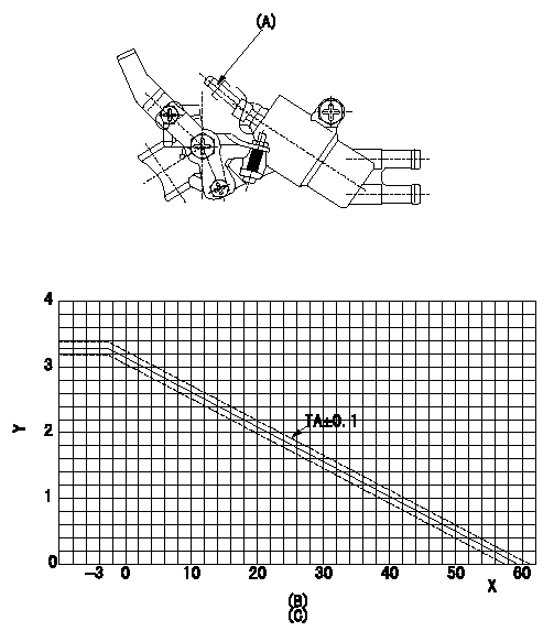
Adjustment of the W-CSD
1. Adjustment of the advance angle of the timer
(1)Determine the timer advance angle using the following graph.
(2)(1) Adjust with the screw (A) so that the timer advance angle determined in the item (1) is obtained.
X:Temperature t (deg C)
Y:Timer stroke TA (mm)
(B): Timer stroke TA (mm):
----------
----------
(B)=TA(mm) (C)=TA=-0.0526t+3.14(-3<=t(degC)) X=t(degC) Y=TA(mm)
----------
----------
(B)=TA(mm) (C)=TA=-0.0526t+3.14(-3<=t(degC)) X=t(degC) Y=TA(mm)
0000001901 W-FICD LEVER ADJUSTMENT
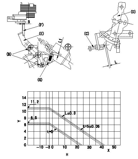
2. Adjustment of the W-FICD
(1)Insert a block gauge L determined from the graph below between the control lever (D) and the idling stopper bolt (C).
(2)Insert a shim S between the W-FICD lever (E) and the control lever (F). Adjust the W-FICD lever (E) so that it contacts the control lever (F) and fix it using bolt (B).
TT
Note:
a) The temperature of wax at the time of adjustment must not exceed a.
b) After completion of the adjustment, confirm that allowance for adjustment of the screw (G) is at least L1.
Y:Control lever L mm
X:Temperature t (deg C)
H:Control lever gap: L (mm)
----------
L=L+-0.05mm S=5+-0.05mm T=3.4~4.9N-m(0.35~0.5kgf-m) a=30degC L1=3mm
----------
S=5mm L1=3mm H=L=-0.256t+10.39(-3<=tdegC)(S=5+-0.05mm)
----------
L=L+-0.05mm S=5+-0.05mm T=3.4~4.9N-m(0.35~0.5kgf-m) a=30degC L1=3mm
----------
S=5mm L1=3mm H=L=-0.256t+10.39(-3<=tdegC)(S=5+-0.05mm)
0000002001 V-FICD ADJUSTMENT
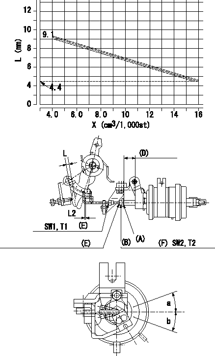
Adjustment of the two stage actuator (FICD).
(C): Stroke adjusting nut
(D): Actuator stroke
(E): Rod position adjusting nut
(F): Stroke adjusting nut
X:Injection quantity
Y:Shim thickness: L
1. Selecting the shim for adjusting the actuator.
(1)Measure the injection quantity at N by inserting the shim L1 between the control lever and the idling stopper bolt.
(2)Select the thickness (L) of the shim for adjusting the actuator using the following formula (refer to the graph.).
Calculation: L
2. Adjustment of the actuator
(1)Mount the actuator to the injection pump.
(2)Position the control lever at the idling position.
(3)Adjust with the nut (D) so that the space between the control lever and the rod becomes L2.
(4)Insert the shim (L) determined above between the control lever and the idling stopper bolt.
(5)Adjust the position of the screw (A) so that the actuator can make its full stroke (Reference value: approx. L3) and fix with the nut (B).
(6)Allowable angle in adjusting the position of the rod: c
----------
N=900r/min L1=6.2mm L:L+-0.1=-0.39167Q+10.667(4.0<=Q<=16.0cm3/1,000st) L2=1+1mm L3=9.6mm c=+-20deg
----------
L2=1+1mm SW1=SW7 T1=1.4~2.0N-m{0.14~0.2kgf-m} SW2=SW8 T2=3.5~5.0N-m{0.35~0.5kgf-m} a=20deg b=20deg
----------
N=900r/min L1=6.2mm L:L+-0.1=-0.39167Q+10.667(4.0<=Q<=16.0cm3/1,000st) L2=1+1mm L3=9.6mm c=+-20deg
----------
L2=1+1mm SW1=SW7 T1=1.4~2.0N-m{0.14~0.2kgf-m} SW2=SW8 T2=3.5~5.0N-m{0.35~0.5kgf-m} a=20deg b=20deg
Information:
General Instructions
These instructions are a review of many items which a serviceman encounters in servicing and maintaining a truck engine.PROBLEM ANALYZING: In analyzing a system malfunction, use this systematic procedure to locate and correct the problem.1. Determine problem.2. List possible causes.3. Devise checks.4. Conduct checks in logical order to determine cause.5. Consider remaining service life against cost of parts and labor.6. Make necessary repair.7. Recheck.SAFETY: Your safety and that of others is always the number one consideration when servicing or maintaining trucks and truck engines. Safety is a matter of thoroughly understanding the job to be done and the application of good common sense. It is not just a matter of "do's" and "don'ts".CLEANLINESS: The most important single item in assuring long engine life is to keep dirt out of vital working parts. Precautions have been taken to safeguard against this. Enclosed compartments, seals and filters have been provided to keep the supply of air, fuel, coolant and lubricants clean. It is important that these safeguards be maintained.Whenever fuel, lubricating oil, coolant lines or air lines are disconnected, clean the point of disconnection as well as the adjacent area. As soon as the disconnection is made, cap, plug or tape the line or opening to prevent entry of foreign material. The same recommendations for cleaning and covering apply when access covers or inspection plates are removed.Clean and inspect all parts. Be sure all passages and holes are open. Cover all parts to keep them clean. Be sure parts are clean when they are installed. Leave new parts in their containers until ready for assembly.REMOVAL AND INSTALLATION: Use a hoist to remove heavy components. Engine removal should be accomplished by using an adjustable lifting beam. All supporting members (chains and cables) should be parallel to each other and as near perpendicular as possible to the top of the object being lifted. When it is necessary to remove a component on an angle, remember that the capacity of an eyebolt diminishes as the angle between the supporting members and the object becomes less than 90°. Eyebolts and brackets should never be bent and should only have stress in tension.Some removals require the use of lifting fixtures to obtain proper balance and to provide safe handling.If a part resists removal, check to be certain all nuts and bolts have been removed and that an adjacent part is not interfering.DISASSEMBLY AND ASSEMBLY: When servicing or repairing the engine, complete each step in turn. Do not partially assemble one part and start assembling some other part. Make all adjustments as recommended. Always check the job after it is completed to see nothing has been overlooked.BOLTS AND BOLT TORQUE: Use bolts of the correct length. A bolt which is too long may "bottom" before the head is tight against the part it is to hold and cause failure. The threads in the assembly can also become damaged when a "long" bolt is used.If a bolt is too short, there may not be enough threads
These instructions are a review of many items which a serviceman encounters in servicing and maintaining a truck engine.PROBLEM ANALYZING: In analyzing a system malfunction, use this systematic procedure to locate and correct the problem.1. Determine problem.2. List possible causes.3. Devise checks.4. Conduct checks in logical order to determine cause.5. Consider remaining service life against cost of parts and labor.6. Make necessary repair.7. Recheck.SAFETY: Your safety and that of others is always the number one consideration when servicing or maintaining trucks and truck engines. Safety is a matter of thoroughly understanding the job to be done and the application of good common sense. It is not just a matter of "do's" and "don'ts".CLEANLINESS: The most important single item in assuring long engine life is to keep dirt out of vital working parts. Precautions have been taken to safeguard against this. Enclosed compartments, seals and filters have been provided to keep the supply of air, fuel, coolant and lubricants clean. It is important that these safeguards be maintained.Whenever fuel, lubricating oil, coolant lines or air lines are disconnected, clean the point of disconnection as well as the adjacent area. As soon as the disconnection is made, cap, plug or tape the line or opening to prevent entry of foreign material. The same recommendations for cleaning and covering apply when access covers or inspection plates are removed.Clean and inspect all parts. Be sure all passages and holes are open. Cover all parts to keep them clean. Be sure parts are clean when they are installed. Leave new parts in their containers until ready for assembly.REMOVAL AND INSTALLATION: Use a hoist to remove heavy components. Engine removal should be accomplished by using an adjustable lifting beam. All supporting members (chains and cables) should be parallel to each other and as near perpendicular as possible to the top of the object being lifted. When it is necessary to remove a component on an angle, remember that the capacity of an eyebolt diminishes as the angle between the supporting members and the object becomes less than 90°. Eyebolts and brackets should never be bent and should only have stress in tension.Some removals require the use of lifting fixtures to obtain proper balance and to provide safe handling.If a part resists removal, check to be certain all nuts and bolts have been removed and that an adjacent part is not interfering.DISASSEMBLY AND ASSEMBLY: When servicing or repairing the engine, complete each step in turn. Do not partially assemble one part and start assembling some other part. Make all adjustments as recommended. Always check the job after it is completed to see nothing has been overlooked.BOLTS AND BOLT TORQUE: Use bolts of the correct length. A bolt which is too long may "bottom" before the head is tight against the part it is to hold and cause failure. The threads in the assembly can also become damaged when a "long" bolt is used.If a bolt is too short, there may not be enough threads
Have questions with 104745-3831?
Group cross 104745-3831 ZEXEL
Mitsubishi
Mitsubishi
Mitsubishi
Mitsubishi
104745-3831
9 460 610 741
MD323062
INJECTION-PUMP ASSEMBLY
4D56
4D56