Information injection-pump assembly
BOSCH
9 460 610 700
9460610700
ZEXEL
104745-3830
1047453830
Rating:
Components :
| 0. | INJECTION-PUMP ASSEMBLY | 104745-3830 |
| 1. | _ | |
| 2. | FUEL INJECTION PUMP | 104645-3830 |
| 3. | NUMBER PLATE | 146958-6500 |
| 4. | _ | 146672-2820 |
| 5. | CAPSULE | |
| 6. | ADJUSTING DEVICE | |
| 7. | NOZZLE AND HOLDER ASSY | 105148-1311 |
| 8. | Nozzle and Holder | MD196607 |
| 9. | Open Pre:MPa(Kqf/cm2) | 14.7{150} |
| 10. | NOZZLE-HOLDER | 105078-0181 |
| 11. | NOZZLE | 105007-1300 |
Scheme ###:
| 1/6. | [1] | 146601-0700 | PACKING RING |
| 6. | [1] | 146100-0220 | SUPPLY PUMP |
| 9. | [1] | 146103-0100 | COVER |
| 10. | [2] | 139104-0000 | FLAT-HEAD SCREW |
| 12. | [1] | 146200-0320 | DRIVE SHAFT |
| 12/1. | [1] | 146200-0300 | DRIVE SHAFT |
| 12/2. | [1] | 146201-0000 | WOODRUFF KEY |
| 12/3. | [2] | 146202-0100 | DAMPER |
| 12/4. | [1] | 146203-0000 | TOOTHED GEAR |
| 17. | [1] | 146204-0000 | PLAIN WASHER |
| 20. | [1] | 146210-3520 | ROLLER SET |
| 24. | [1] | 146303-0000 | BEARING PIN |
| 25. | [1] | 146304-0000 | BEARING PIN |
| 26. | [1] | 146305-0000 | CLAMPING BAND |
| 27. | [1] | 146205-0000 | SLOTTED WASHER |
| 29. | [1] | 146220-0020 | CAM PLATE |
| 30. | [1] | 146600-0800 | O-RING |
| 31. | [1] | 146311-6320 | PUMP PLUNGER |
| 32. | [1] | 146301-0000 | SLIDING PIECE |
| 34. | [1] | 146312-2900 | COMPRESSION SPRING |
| 34B. | [1] | 146312-2800 | COMPRESSION SPRING |
| 34C. | [1] | 146312-3200 | COMPRESSION SPRING |
| 35/1. | [1] | 146690-3200 | SHIM D11.5&9.4T0.1 |
| 35/1. | [1] | 146690-3300 | SHIM D11.5&9.4T0.2 |
| 35/1. | [1] | 146690-3400 | SHIM D11.5&9.4T0.25 |
| 35/1. | [1] | 146690-3500 | SHIM D11.5&9.4T1.0 |
| 35/1. | [1] | 146690-4100 | SHIM D11.5&9.4T2 |
| 35/1. | [1] | 146690-4200 | SHIM D11.5&9.4T0.5 |
| 35/1. | [1] | 146690-4300 | SHIM D11.5&9.4T0.75 |
| 36. | [1] | 146600-0800 | O-RING |
| 37. | [1] | 146310-1600 | COVER |
| 38. | [2] | 146620-5000 | BLEEDER SCREW |
| 39. | [1] | 146310-0100 | COVER |
| 40. | [2] | 146620-5000 | BLEEDER SCREW |
| 41. | [1] | 146312-1900 | COMPRESSION SPRING |
| 42. | [1] | 146602-8500 | PLAIN WASHER |
| 43. | [1] | 146230-0000 | SHIM |
| 44. | [1] | 146230-0100 | PLAIN WASHER |
| 45. | [1] | 146231-0001 | SLOTTED WASHER |
| 47. | [2] | 146233-0000 | SLOTTED WASHER |
| 48/1. | [1] | 146603-0000 | SHIM D17.0&5.2T0.50 |
| 48/1. | [1] | 146603-0100 | SHIM D17.0&5.2T0.80 |
| 48/1. | [1] | 146603-0200 | SHIM D17.0&5.2T1.00 |
| 48/1. | [1] | 146603-0300 | SHIM D17.0&5.2T1.20 |
| 48/1. | [1] | 146603-0400 | SHIM D17.0&5.2T1.50 |
| 48/1. | [1] | 146603-0500 | SHIM D17.0&5.2T1.80 |
| 48/1. | [1] | 146603-0600 | SHIM D17.0&5.2T2.00 |
| 48/1. | [1] | 146690-1400 | SHIM D17&5.2T0.9 |
| 48/1. | [1] | 146690-1500 | SHIM D17&5.2T1.1 |
| 48/1. | [1] | 146690-1600 | SHIM D17&5.2T1.3 |
| 48/1. | [1] | 146690-1700 | SHIM D17&5.2T1.4 |
| 48/1. | [1] | 146690-1800 | SHIM D17&5.2T1.6 |
| 48/1. | [1] | 146690-1900 | SHIM D17&5.2T1.7 |
| 48/1. | [1] | 146690-5800 | SHIM |
| 48/1. | [1] | 146690-5900 | SHIM |
| 48/1. | [1] | 146690-6000 | SHIM |
| 48/1. | [1] | 146690-6100 | SHIM |
| 48/1. | [1] | 146690-6200 | SHIM |
| 48/1. | [1] | 146690-6300 | SHIM |
| 48/1. | [1] | 146690-6400 | SHIM |
| 48/1. | [1] | 146690-6500 | SHIM |
| 48/1. | [1] | 146690-6600 | SHIM |
| 48/1. | [1] | 146690-6700 | SHIM |
| 48/1. | [1] | 146690-6800 | SHIM |
| 48/1. | [1] | 146690-6900 | SHIM |
| 48/1. | [1] | 146690-7000 | SHIM |
| 48/1. | [1] | 146690-7100 | SHIM |
| 48/1. | [1] | 146690-7200 | SHIM |
| 48/1. | [1] | 146690-7300 | SHIM |
| 48/1. | [1] | 146690-7400 | SHIM |
| 48/1. | [1] | 146690-7500 | SHIM |
| 48/1. | [1] | 146690-7800 | SHIM |
| 49. | [2] | 146234-0020 | GUIDE PIN |
| 50. | [1] | 146401-3320 | HYDRAULIC HEAD |
| 50. | [1] | 146401-3320 | HYDRAULIC HEAD |
| 50. | [1] | 146401-3320 | HYDRAULIC HEAD |
| 51. | [1] | 146600-0000 | O-RING |
| 52/1. | [1] | 146420-0000 | SHIM D9.5&3.0T1.90 |
| 52/1. | [1] | 146420-0100 | SHIM D9.5&3.0T1.92 |
| 52/1. | [1] | 146420-0200 | SHIM D9.5&3.0T1.94 |
| 52/1. | [1] | 146420-0300 | SHIM D9.5&3.0T1.96 |
| 52/1. | [1] | 146420-0400 | SHIM D9.5&3.0T1.98 |
| 52/1. | [1] | 146420-0500 | SHIM D9.5&3.0T2.00 |
| 52/1. | [1] | 146420-0600 | SHIM D9.5&3.0T2.02 |
| 52/1. | [1] | 146420-0700 | SHIM D9.5&3.0T2.04 |
| 52/1. | [1] | 146420-0800 | SHIM D9.5&3.0T2.06 |
| 52/1. | [1] | 146420-0900 | SHIM D9.5&3.0T2.08 |
| 52/1. | [1] | 146420-1000 | SHIM D9.5&3.0T2.10 |
| 52/1. | [1] | 146420-1100 | SHIM D9.5&3.0T2.12 |
| 52/1. | [1] | 146420-1200 | SHIM D9.5&3.0T2.14 |
| 52/1. | [1] | 146420-1300 | SHIM D9.5&3.0T2.16 |
| 52/1. | [1] | 146420-1400 | SHIM D9.5&3.0T2.18 |
| 52/1. | [1] | 146420-1500 | SHIM D9.5&3.0T2.20 |
| 52/1. | [1] | 146420-1600 | SHIM D9.5&3.0T2.22 |
| 52/1. | [1] | 146420-1700 | SHIM D9.5&3.0T2.24 |
| 52/1. | [1] | 146420-1800 | SHIM D9.5&3.0T2.26 |
| 52/1. | [1] | 146420-1900 | SHIM D9.5&3.0T2.28 |
| 52/1. | [1] | 146420-2000 | SHIM D9.5&3.0T2.30 |
| 52/1. | [1] | 146420-2100 | SHIM D9.5&3.0T2.32 |
| 52/1. | [1] | 146420-2200 | SHIM D9.5&3.0T2.34 |
| 52/1. | [1] | 146420-2300 | SHIM D9.5&3.0T2.36 |
| 52/1. | [1] | 146420-2400 | SHIM D9.5&3.0T2.38 |
| 52/1. | [1] | 146420-2500 | SHIM D9.5&3.0T2.40 |
| 52/1. | [1] | 146420-2600 | SHIM D9.5&3.0T2.42 |
| 52/1. | [1] | 146420-2700 | SHIM D9.5&3.0T2.44 |
| 52/1. | [1] | 146420-2800 | SHIM D9.5&3.0T2.46 |
| 52/1. | [1] | 146420-2900 | SHIM D9.5&3.0T2.48 |
| 52/1. | [1] | 146420-3000 | SHIM D9.5&3.0T2.50 |
| 52/1. | [1] | 146420-3100 | SHIM D9.5&3.0T2.52 |
| 52/1. | [1] | 146420-3200 | SHIM D9.5&3.0T2.54 |
| 52/1. | [1] | 146420-3300 | SHIM D9.5&3.0T2.56 |
| 52/1. | [1] | 146420-3400 | SHIM D9.5&3.0T2.58 |
| 52/1. | [1] | 146420-3500 | SHIM D9.5&3.0T2.60 |
| 52/1. | [1] | 146420-3600 | SHIM D9.5&3.0T2.62 |
| 52/1. | [1] | 146420-3700 | SHIM D9.5&3.0T2.64 |
| 52/1. | [1] | 146420-3800 | SHIM D9.5&3.0T2.66 |
| 52/1. | [1] | 146420-3900 | SHIM D9.5&3.0T2.68 |
| 52/1. | [1] | 146420-4000 | SHIM D9.5&3.0T2.70 |
| 52/1. | [1] | 146420-4100 | SHIM D9.5&3.0T2.72 |
| 52/1. | [1] | 146420-4200 | SHIM D9.5&3.0T2.74 |
| 52/1. | [1] | 146420-4300 | SHIM D9.5&3.0T2.76 |
| 52/1. | [1] | 146420-4400 | SHIM D9.5&3.0T2.78 |
| 52/1. | [1] | 146420-4500 | SHIM D9.5&3.0T2.80 |
| 52/1. | [1] | 146420-4600 | SHIM D9.5&3.0T2.82 |
| 52/1. | [1] | 146420-4700 | SHIM D9.5&3.0T2.84 |
| 52/1. | [1] | 146420-4800 | SHIM D9.5&3.0T2.86 |
| 52/1. | [1] | 146420-4900 | SHIM D9.5&3.0T2.88 |
| 52/1. | [1] | 146420-5000 | SHIM D9.5&3.0T2.90 |
| 52/1. | [1] | 146420-5100 | SHIM D9.5&3.0T1.74 |
| 52/1. | [1] | 146420-5200 | SHIM D9.5&3.0T1.76 |
| 52/1. | [1] | 146420-5300 | SHIM D9.5&3.0T1.78 |
| 52/1. | [1] | 146420-5400 | SHIM D9.5&3.0T1.80 |
| 52/1. | [1] | 146420-5500 | SHIM D9.5&3.0T1.82 |
| 52/1. | [1] | 146420-5600 | SHIM D9.5&3.0T1.84 |
| 52/1. | [1] | 146420-5700 | SHIM D9.5&3.0T1.86 |
| 52/1. | [1] | 146420-5800 | SHIM D9.5&3.0T1.88 |
| 54. | [4] | 146433-0100 | GASKET D12&6.4T1.00 |
| 55. | [4] | 146430-2020 | DELIVERY-VALVE ASSEMBLY |
| 56. | [4] | 146432-0000 | COMPRESSION SPRING |
| 58. | [4] | 146440-0320 | FITTING |
| 60. | [3] | 139106-0100 | FLAT-HEAD SCREW |
| 66. | [1] | 146600-0100 | O-RING |
| 67. | [1] | 146703-5620 | COMPENSATOR,MANIFOLD-PRES |
| 67/1. | [1] | 146805-7320 | GOVERNOR COVER |
| 67/14. | [1] | 146621-1700 | UNION NUT |
| 67/16. | [1] | 146526-3000 | BLEEDER SCREW |
| 67/23. | [1] | 146925-7520 | BRACKET |
| 67/24. | [2] | 010206-2240 | HEX-SOCKET-HEAD CAP SCREW |
| 67/31. | [1] | 146710-0700 | BUSHING |
| 67/32. | [1] | 146711-0000 | PLATE |
| 67/33. | [1] | 139218-0400 | UNION NUT |
| 67/34. | [1] | 146712-0700 | BEARING PIN |
| 67/35. | [1] | 146621-0300 | UNION NUT |
| 67/36. | [1] | 146600-1400 | O-RING |
| 67/37. | [1] | 146710-0100 | BUSHING |
| 67/38. | [1] | 139506-0200 | GASKET D8.9&6.8T1.00 |
| 67/39. | [1] | 146620-0300 | CAPSULE |
| 67/40. | [1] | 026512-1540 | GASKET D15.4&12.2T1.50 |
| 67/41. | [1] | 146713-4300 | ADJUSTING PIN |
| 67/42. | [2] | 146714-0200 | PLATE |
| 67/43. | [1] | 146715-0300 | DIAPHRAGM |
| 67/44. | [1] | 139306-0100 | LOCKING WASHER |
| 67/45. | [1] | 013030-6040 | UNION NUT M6P1H3.6 |
| 67/46. | [1] | 146716-0000 | UNION NUT |
| 67/47. | [1] | 146717-3600 | COILED SPRING |
| 67/48/1. | [1] | 146720-3000 | SPACER BUSHING L3.7 |
| 67/48/1. | [1] | 146720-3100 | SPACER BUSHING L3.9 |
| 67/48/1. | [1] | 146720-3200 | SPACER BUSHING L4.1 |
| 67/48/1. | [1] | 146720-3300 | SPACER BUSHING L4.3 |
| 67/48/1. | [1] | 146720-3400 | SPACER BUSHING L4.5 |
| 67/48/1. | [1] | 146720-3500 | SPACER BUSHING L4.7 |
| 67/48/1. | [1] | 146720-3600 | SPACER BUSHING L4.9 |
| 67/48/1. | [1] | 146720-3700 | SPACER BUSHING L5.1 |
| 67/48/1. | [1] | 146720-3800 | SPACER BUSHING L5.3 |
| 67/48/1. | [1] | 146720-3900 | SPACER BUSHING L5.5 |
| 67/48/1. | [1] | 146720-4000 | SPACER BUSHING L5.7 |
| 67/48/1. | [1] | 146720-4100 | SPACER BUSHING L5.9 |
| 67/48/1. | [1] | 146720-4200 | SPACER BUSHING L6.1 |
| 67/48/1. | [1] | 146720-4300 | SPACER BUSHING L6.3 |
| 67/48/1. | [1] | 146720-4400 | SPACER BUSHING L6.5 |
| 67/48/1. | [1] | 146720-8900 | SPACER BUSHING L6.7 |
| 67/48/1. | [1] | 146720-9000 | SPACER BUSHING L6.9 |
| 67/48/1. | [1] | 146720-9100 | SPACER BUSHING L7.1 |
| 67/48/1. | [1] | 146720-9200 | SPACER BUSHING L7.3 |
| 67/48/1. | [1] | 146720-9300 | SPACER BUSHING L7.5 |
| 67/48/1. | [1] | 146720-9400 | SPACER BUSHING L7.7 |
| 67/48/1. | [1] | 146720-9500 | SPACER BUSHING L7.9 |
| 67/48/1. | [1] | 146720-9600 | SPACER BUSHING L8.1 |
| 67/48/1. | [1] | 146720-9700 | SPACER BUSHING L8.3 |
| 67/48/1. | [1] | 146720-9800 | SPACER BUSHING L8.5 |
| 67/48/1. | [1] | 146720-9900 | SPACER BUSHING L3.6 |
| 67/48/1. | [1] | 146725-0000 | SPACER BUSHING L3.8 |
| 67/48/1. | [1] | 146725-0100 | SPACER BUSHING L4.0 |
| 67/48/1. | [1] | 146725-0200 | SPACER BUSHING L4.2 |
| 67/48/1. | [1] | 146725-0300 | SPACER BUSHING L4.4 |
| 67/48/1. | [1] | 146725-0400 | SPACER BUSHING L4.6 |
| 67/48/1. | [1] | 146725-0500 | SPACER BUSHING L4.8 |
| 67/48/1. | [1] | 146725-0600 | SPACER BUSHING L5.0 |
| 67/48/1. | [1] | 146725-0700 | SPACER BUSHING L5.2 |
| 67/48/1. | [1] | 146725-0800 | SPACER BUSHING L5.4 |
| 67/48/1. | [1] | 146725-0900 | SPACER BUSHING L5.6 |
| 67/48/1. | [1] | 146725-1000 | SPACER BUSHING L5.8 |
| 67/48/1. | [1] | 146725-1100 | SPACER BUSHING L6.0 |
| 67/48/1. | [1] | 146725-1200 | SPACER BUSHING L6.2 |
| 67/48/1. | [1] | 146725-1300 | SPACER BUSHING L6.4 |
| 67/48/1. | [1] | 146725-1400 | SPACER BUSHING L6.6 |
| 67/48/1. | [1] | 146725-1500 | SPACER BUSHING L6.8 |
| 67/48/1. | [1] | 146725-1600 | SPACER BUSHING L7.0 |
| 67/48/1. | [1] | 146725-1700 | SPACER BUSHING L7.2 |
| 67/48/1. | [1] | 146725-1800 | SPACER BUSHING L7.4 |
| 67/48/1. | [1] | 146725-1900 | SPACER BUSHING L7.6 |
| 67/48/1. | [1] | 146725-2000 | SPACER BUSHING L7.8 |
| 67/48/1. | [1] | 146725-2100 | SPACER BUSHING L8.0 |
| 67/48/1. | [1] | 146725-2200 | SPACER BUSHING L8.2 |
| 67/48/1. | [1] | 146725-2300 | SPACER BUSHING L8.4 |
| 67/48/1. | [1] | 146725-2400 | SPACER BUSHING L8.6 |
| 67/49. | [1] | 146721-3720 | COVER |
| 67/50. | [1] | 146722-0200 | FLAT-HEAD SCREW |
| 67/51. | [1] | 146600-0300 | O-RING |
| 67/53. | [1] | 013020-6040 | UNION NUT M6P1H5 |
| 67/54. | [2] | 139006-4700 | BLEEDER SCREW |
| 67/55. | [2] | 139006-4600 | BLEEDER SCREW |
| 67/56. | [1] | 146723-0300 | CONTROL LEVER |
| 67/57. | [1] | 146712-0100 | BEARING PIN |
| 67/58. | [2] | 146620-0600 | CAPSULE |
| 67/59. | [2] | 026506-1040 | GASKET D9.9&6.2T1 |
| 67/60. | [1] | 146724-0300 | ELEMENT |
| 67/61. | [1] | 146724-0600 | CAPSULE |
| 67/78. | [1] | 146600-4400 | SEAL RING |
| 67/96. | [1] | 146659-6320 | CLAMPING BAND |
| 67/102. | [1] | 146932-6822 | BRACKET |
| 67/109. | [1] | 146649-2200 | SPACER BUSHING |
| 67/112. | [1] | 146926-5520 | BRACKET |
| 67/200. | [1] | 139308-0300 | PLAIN WASHER |
| 67/201. | [1] | 146545-3400 | THREADED PIN L53.00 |
| 67/201B. | [1] | 146545-3500 | THREADED PIN L55.00 |
| 67/201C. | [1] | 146545-3600 | THREADED PIN L57.00 |
| 67/202. | [1] | 139208-0900 | UNION NUT |
| 67/203. | [1] | 146600-1200 | O-RING |
| 68. | [1] | 146810-0120 | CONTROL SHAFT |
| 69. | [1] | 139310-0200 | PLAIN WASHER |
| 72. | [1] | 146830-7120 | CONTROL LEVER |
| 72B. | [1] | 146830-7220 | CONTROL LEVER |
| 73. | [1] | 014110-6440 | LOCKING WASHER |
| 75. | [1] | 013020-6040 | UNION NUT M6P1H5 |
| 95. | [1] | 146550-1520 | FULCRUM LEVER |
| 104. | [2] | 146568-0000 | SLOTTED SPRING PIN |
| 105. | [2] | 026508-1140 | GASKET D11.4&8.2T1 |
| 106. | [2] | 146588-0500 | COILED SPRING |
| 107. | [1] | 146569-0300 | UNION NUT |
| 108. | [1] | 146570-0420 | GOVERNOR SHAFT |
| 109. | [1] | 146600-0400 | O-RING |
| 110/1. | [1] | 146571-0000 | SHIM D20.2&8.3T1.05 |
| 110/1. | [1] | 146571-0100 | SHIM D20.2&8.3T1.25 |
| 110/1. | [1] | 146571-0200 | SHIM D20.2&8.3T1.45 |
| 110/1. | [1] | 146571-0300 | SHIM D20.2&8.3T1.65 |
| 110/1. | [1] | 146571-0400 | SHIM D20.2&8.3T1.85 |
| 110/1. | [1] | 146571-0500 | SHIM D20.2&8.3T1.15 |
| 110/1. | [1] | 146571-0600 | SHIM D20.2&8.3T1.35 |
| 110/1. | [1] | 146571-0700 | SHIM D20.2&8.3T1.55 |
| 110/1. | [1] | 146571-0800 | SHIM D20.2&8.3T1.75 |
| 111. | [1] | 146602-0600 | PLAIN WASHER D20&8.4T1.40 |
| 112. | [1] | 146572-0020 | FLYWEIGHT ASSEMBLY |
| 114. | [1] | 146602-0500 | PLAIN WASHER D17&6.4T1.60 |
| 115. | [1] | 146875-8300 | SLIDING SLEEVE |
| 116. | [1] | 146576-0000 | SEALING CAP |
| 117/1. | [1] | 146577-1800 | PLUG L2.10 |
| 117/1. | [1] | 146577-1900 | PLUG L2.30 |
| 117/1. | [1] | 146577-2000 | PLUG L2.50 |
| 117/1. | [1] | 146577-2100 | PLUG L2.70 |
| 117/1. | [1] | 146577-2200 | PLUG L2.90 |
| 117/1. | [1] | 146577-2300 | PLUG L3.10 |
| 117/1. | [1] | 146577-2400 | PLUG L3.30 |
| 117/1. | [1] | 146577-2500 | PLUG L3.50 |
| 117/1. | [1] | 146577-2600 | PLUG L3.70 |
| 117/1. | [1] | 146577-2700 | PLUG L3.90 |
| 117/1. | [1] | 146577-2800 | PLUG L4.10 |
| 117/1. | [1] | 146577-2900 | PLUG L4.30 |
| 117/1. | [1] | 146577-3000 | PLUG L4.50 |
| 117/1. | [1] | 146577-3100 | PLUG L4.70 |
| 117/1. | [1] | 146577-3200 | PLUG L4.90 |
| 117/1. | [1] | 146577-3300 | PLUG L5.10 |
| 117/1. | [1] | 146577-6700 | PLUG L2.2 |
| 117/1. | [1] | 146577-6800 | PLUG L2.4 |
| 117/1. | [1] | 146577-6900 | PLUG L2.6 |
| 117/1. | [1] | 146577-7000 | PLUG L2.8 |
| 117/1. | [1] | 146577-7100 | PLUG L3.0 |
| 117/1. | [1] | 146577-7200 | PLUG L3.2 |
| 117/1. | [1] | 146577-7300 | PLUG L3.4 |
| 117/1. | [1] | 146577-7400 | PLUG L3.6 |
| 117/1. | [1] | 146577-7500 | PLUG L3.8 |
| 117/1. | [1] | 146577-7600 | PLUG L4.0 |
| 117/1. | [1] | 146577-7700 | PLUG L4.2 |
| 117/1. | [1] | 146577-7800 | PLUG L4.4 |
| 117/1. | [1] | 146577-7900 | PLUG L4.6 |
| 117/1. | [1] | 146577-8000 | PLUG L4.8 |
| 117/1. | [1] | 146577-8100 | PLUG L5.0 |
| 117/1. | [1] | 146877-0000 | PLUG L5.2 |
| 117/1. | [1] | 146877-0100 | PLUG L5.3 |
| 117/1. | [1] | 146877-0200 | PLUG L5.4 |
| 117/1. | [1] | 146877-0300 | PLUG L5.5 |
| 117/1. | [1] | 146877-4700 | PLUG |
| 117/1. | [1] | 146877-4800 | PLUG |
| 117/1. | [1] | 146877-4900 | PLUG |
| 117/1. | [1] | 146877-5000 | PLUG |
| 123. | [4] | 146620-0500 | HEX-SOCKET-HEAD CAP SCREW |
| 130. | [1] | 146421-0020 | CAPSULE |
| 130/2. | [1] | 026508-1140 | GASKET D11.4&8.2T1 |
| 130/3. | [1] | 146422-0000 | BLEEDER SCREW |
| 130/4. | [1] | 146600-0500 | O-RING |
| 133. | [1] | 146600-0600 | O-RING |
| 134. | [1] | 146600-0700 | O-RING |
| 135. | [1] | 146110-0220 | CONTROL VALVE |
| 135/5. | [1] | 146114-0000 | SPRING WASHER |
| 136. | [1] | 146120-0020 | OVER FLOW VALVE |
| 137. | [2] | 026512-1840 | GASKET D17.9&12.2T1.50 |
| 138. | [1] | 146666-7220 | INLET UNION |
| 200. | [1] | 146206-0100 | COILED SPRING |
| 205. | [1] | 029470-4030 | WOODRUFF KEY |
| 217. | [1] | 146542-5300 | SLOTTED WASHER |
| 218. | [1] | 146592-2500 | COILED SPRING |
| 219. | [1] | 146541-3000 | BUSHING |
| 220. | [1] | 146592-2600 | COILED SPRING |
| 224. | [1] | 139006-4700 | BLEEDER SCREW |
| 230. | [1] | 146931-3400 | BRACKET |
| 231. | [1] | 139006-4600 | BLEEDER SCREW |
| 234. | [1] | 139006-4800 | BLEEDER SCREW |
| 235. | [1] | 146931-6100 | BRACKET |
| 237. | [1] | 146620-0200 | HEX-SOCKET-HEAD CAP SCREW |
| 240. | [1] | 146688-0120 | PULLING ELECTROMAGNET |
| 240/8. | [1] | 146600-1700 | O-RING |
| 242. | [1] | 407911-1410 | CONTROL UNIT |
| 243. | [1] | 146621-4900 | UNION NUT |
| 245. | [3] | 026512-1840 | GASKET D17.9&12.2T1.50 |
| 246. | [1] | 139812-1900 | EYE BOLT |
| 247. | [1] | 146666-7420 | INLET UNION |
| 248. | [1] | 146614-0200 | SPACER BUSHING |
| 251. | [1] | 146125-0101 | FILTER |
| 252. | [1] | 146125-0200 | COILED SPRING |
| 275. | [1] | 146612-4800 | BRACKET |
| 276. | [2] | 010010-1640 | BLEEDER SCREW M10P1.5L16 4T |
| 280. | [1] | 146361-3420 | START ADVANCE ASSY |
| 281. | [1] | 146600-0800 | O-RING |
| 283. | [1] | 146679-2821 | ADJUSTING DEVICE |
| 284. | [2] | 139005-0400 | BLEEDER SCREW |
| 360. | [1] | 146649-8800 | BUSHING |
| 361. | [1] | 146649-8900 | CAP |
| 362. | [2] | 146620-8402 | BLEEDER SCREW |
| 800S. | [1] | 146018-4820 | PUMP HOUSING |
| 800S/1/6. | [1] | 146601-0700 | PACKING RING |
| 804S. | [1] | 146232-0320 | COMPRESSION SPRING |
| 805S. | [1] | 146574-0120 | PARTS SET |
| 810S. | [1] | 146600-1120 | REPAIR SET |
| 835S. | [1] | 146598-1000 | CAP |
| 836S/1. | [1] | 146598-0600 | CAP L18 |
| 836S/1. | [1] | 146598-0700 | CAP L21 |
| 836S/1. | [1] | 146598-0800 | CAP L24 |
| 836S/1. | [1] | 146598-0900 | CAP L27 |
| 903. | [1] | 146672-2820 | PULSE GENERATOR |
| 903/2. | [1] | 146600-1300 | O-RING &13W1.9 |
| 906. | [1] | 146958-6500 | NAMEPLATE |
| 910S. | [1] | 146600-4220 | PARTS SET |
| 910S. | [1] | 146600-4220 | PARTS SET |
| 911S. | [1] | 146672-2820 | PULSE GENERATOR |
| 911S/2. | [1] | 146600-1300 | O-RING &13W1.9 |
| 912S. | [1] | 026508-1140 | GASKET D11.4&8.2T1 |
| 913S. | [1] | 146422-0000 | BLEEDER SCREW |
| 914S. | [1] | 146699-0620 | VALVE SET |
| 914S. | [1] | 146699-0620 | VALVE SET |
| 914S. | [1] | 146699-0620 | VALVE SET |
| 916S. | [1] | 025804-1610 | WOODRUFF KEY |
Include in #2:
104745-3830
as INJECTION-PUMP ASSEMBLY
Cross reference number
BOSCH
9 460 610 700
9460610700
ZEXEL
104745-3830
1047453830
Zexel num
Bosch num
Firm num
Name
Calibration Data:
Adjustment conditions
Test oil
1404 Test oil ISO4113orSAEJ967d
1404 Test oil ISO4113orSAEJ967d
Test oil temperature
degC
45
45
50
Nozzle
105780-0060
Bosch type code
NP-DN0SD1510
Nozzle holder
105780-2150
Opening pressure
MPa
13
13
13.3
Opening pressure
kgf/cm2
133
133
136
Injection pipe
157805-7320
Injection pipe
Inside diameter - outside diameter - length (mm) mm 2-6-450
Inside diameter - outside diameter - length (mm) mm 2-6-450
Joint assembly
157641-4720
Tube assembly
157641-4020
Transfer pump pressure
kPa
20
20
20
Transfer pump pressure
kgf/cm2
0.2
0.2
0.2
Direction of rotation (viewed from drive side)
Right R
Right R
Injection timing adjustment
Pump speed
r/min
750
750
750
Boost pressure
kPa
0
0
0
Boost pressure
mmHg
0
0
0
Average injection quantity
mm3/st.
52.6
52.1
53.1
Difference in delivery
mm3/st.
4
Basic
*
Oil temperature
degC
50
48
52
Remarks
NA
NA
Injection timing adjustment_02
Pump speed
r/min
750
750
750
Boost pressure
kPa
44
42.7
45.3
Boost pressure
mmHg
330
320
340
Average injection quantity
mm3/st.
62.6
62.1
63.1
Difference in delivery
mm3/st.
5
Basic
*
Oil temperature
degC
50
48
52
Remarks
CBS
CBS
Injection timing adjustment_03
Pump speed
r/min
1250
1250
1250
Boost pressure
kPa
73.3
72
74.6
Boost pressure
mmHg
550
540
560
Average injection quantity
mm3/st.
76.6
76.1
77.1
Difference in delivery
mm3/st.
6
Basic
*
Oil temperature
degC
50
48
52
Remarks
Full
Full
Injection timing adjustment_04
Pump speed
r/min
750
750
750
Boost pressure
kPa
0
0
0
Boost pressure
mmHg
0
0
0
Average injection quantity
mm3/st.
52.6
51.6
53.6
Oil temperature
degC
50
48
52
Injection timing adjustment_05
Pump speed
r/min
750
750
750
Boost pressure
kPa
44
42.7
45.3
Boost pressure
mmHg
330
320
340
Average injection quantity
mm3/st.
62.6
61.6
63.6
Basic
*
Oil temperature
degC
50
48
52
Remarks
CBS
CBS
Injection timing adjustment_06
Pump speed
r/min
1000
1000
1000
Boost pressure
kPa
73.3
72
74.6
Boost pressure
mmHg
550
540
560
Average injection quantity
mm3/st.
77
74.5
79.5
Oil temperature
degC
50
48
52
Injection timing adjustment_07
Pump speed
r/min
1250
1250
1250
Boost pressure
kPa
73.3
72
74.6
Boost pressure
mmHg
550
540
560
Average injection quantity
mm3/st.
76.6
75.6
77.6
Difference in delivery
mm3/st.
6.5
Basic
*
Oil temperature
degC
50
48
52
Remarks
Full
Full
Injection timing adjustment_08
Pump speed
r/min
2100
2100
2100
Boost pressure
kPa
73.3
72
74.6
Boost pressure
mmHg
550
540
560
Average injection quantity
mm3/st.
65
62.5
67.5
Oil temperature
degC
52
50
54
Injection quantity adjustment
Pump speed
r/min
2650
2650
2650
Boost pressure
kPa
73.3
72
74.6
Boost pressure
mmHg
550
540
560
Average injection quantity
mm3/st.
27.9
24.9
30.9
Difference in delivery
mm3/st.
8.5
Basic
*
Oil temperature
degC
55
52
58
Injection quantity adjustment_02
Pump speed
r/min
2950
2950
2950
Boost pressure
kPa
73.3
72
74.6
Boost pressure
mmHg
550
540
560
Average injection quantity
mm3/st.
5
Oil temperature
degC
55
52
58
Injection quantity adjustment_03
Pump speed
r/min
2650
2650
2650
Boost pressure
kPa
73.3
72
74.6
Boost pressure
mmHg
550
540
560
Average injection quantity
mm3/st.
27.9
22.9
32.9
Difference in delivery
mm3/st.
9
Basic
*
Oil temperature
degC
55
52
58
Governor adjustment
Pump speed
r/min
375
375
375
Boost pressure
kPa
0
0
0
Boost pressure
mmHg
0
0
0
Average injection quantity
mm3/st.
19.4
17.9
20.9
Difference in delivery
mm3/st.
2
Basic
*
Oil temperature
degC
48
46
50
Governor adjustment_02
Pump speed
r/min
375
375
375
Boost pressure
kPa
0
0
0
Boost pressure
mmHg
0
0
0
Average injection quantity
mm3/st.
19.4
17.4
21.4
Difference in delivery
mm3/st.
2.5
Basic
*
Oil temperature
degC
48
46
50
Governor adjustment_03
Pump speed
r/min
750
750
750
Boost pressure
kPa
0
0
0
Boost pressure
mmHg
0
0
0
Average injection quantity
mm3/st.
8
Oil temperature
degC
50
48
52
Timer adjustment
Pump speed
r/min
100
100
100
Boost pressure
kPa
0
0
0
Boost pressure
mmHg
0
0
0
Average injection quantity
mm3/st.
75
65
85
Basic
*
Oil temperature
degC
48
46
50
Remarks
IDLE
IDLE
Timer adjustment_02
Pump speed
r/min
100
100
100
Boost pressure
kPa
0
0
0
Boost pressure
mmHg
0
0
0
Average injection quantity
mm3/st.
75
65
85
Oil temperature
degC
48
46
50
Remarks
IDLE
IDLE
Speed control lever angle
Pump speed
r/min
375
375
375
Boost pressure
kPa
0
0
0
Boost pressure
mmHg
0
0
0
Average injection quantity
mm3/st.
0
0
0
Oil temperature
degC
48
46
50
Remarks
Magnet OFF at idling position
Magnet OFF at idling position
0000000901
Pump speed
r/min
1250
1250
1250
Boost pressure
kPa
73.3
72
74.6
Boost pressure
mmHg
550
540
560
Overflow quantity
cm3/min
420
290
550
Oil temperature
degC
50
48
52
Stop lever angle
Pump speed
r/min
1250
1250
1250
Boost pressure
kPa
73.3
72
74.6
Boost pressure
mmHg
550
540
560
Pressure
kPa
549
520
578
Pressure
kgf/cm2
5.6
5.3
5.9
Basic
*
Oil temperature
degC
50
48
52
0000001101
Pump speed
r/min
1250
1250
1250
Boost pressure
kPa
73.3
72
74.6
Boost pressure
mmHg
550
540
560
Timer stroke
mm
4.6
4.4
4.8
Basic
*
Oil temperature
degC
50
48
52
_02
Pump speed
r/min
500
500
500
Boost pressure
kPa
73.3
72
74.6
Boost pressure
mmHg
550
540
560
Timer stroke
mm
1.2
0.6
1.8
Oil temperature
degC
48
46
50
_03
Pump speed
r/min
1000
1000
1000
Boost pressure
kPa
73.3
72
74.6
Boost pressure
mmHg
550
540
560
Timer stroke
mm
3.5
2.9
4.1
Oil temperature
degC
50
48
52
_04
Pump speed
r/min
1250
1250
1250
Boost pressure
kPa
73.3
72
74.6
Boost pressure
mmHg
550
540
560
Timer stroke
mm
4.6
4.2
5
Basic
*
Oil temperature
degC
50
48
52
_05
Pump speed
r/min
1500
1500
1500
Boost pressure
kPa
73.3
72
74.6
Boost pressure
mmHg
550
540
560
Timer stroke
mm
5.6
5
6.2
Oil temperature
degC
50
48
52
_06
Pump speed
r/min
2100
2100
2100
Boost pressure
kPa
73.3
72
74.6
Boost pressure
mmHg
550
540
560
Timer stroke
mm
7.8
7.2
8.4
Oil temperature
degC
52
50
54
0000001201
Max. applied voltage
V
8
8
8
Test voltage
V
13
12
14
0000001401
Pump speed
r/min
1250
1250
1250
Boost pressure
kPa
73.3
72
74.6
Boost pressure
mmHg
550
540
560
Average injection quantity
mm3/st.
48
47.5
48.5
Timer stroke TA
mm
3.9
3.7
4.1
Timer stroke variation dT
mm
0.7
0.7
0.7
Basic
*
Oil temperature
degC
50
48
52
_02
Pump speed
r/min
1250
1250
1250
Boost pressure
kPa
73.3
72
74.6
Boost pressure
mmHg
550
540
560
Average injection quantity
mm3/st.
48
47
49
Timer stroke TA
mm
3.9
3.5
4.3
Basic
*
Oil temperature
degC
50
48
52
_03
Pump speed
r/min
1250
1250
1250
Boost pressure
kPa
73.3
72
74.6
Boost pressure
mmHg
550
540
560
Average injection quantity
mm3/st.
32
31
33
Timer stroke TA
mm
2.5
1.9
3.1
Oil temperature
degC
50
48
52
Timing setting
K dimension
mm
3.3
3.2
3.4
KF dimension
mm
5.8
5.7
5.9
MS dimension
mm
1.2
1.1
1.3
Control lever angle alpha
deg.
61
57
65
Control lever angle beta
deg.
42
37
47
Test data Ex:
0000001801 W-CSD ADJUSTMENT
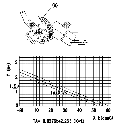
Adjustment of the W-CSD
1. Adjustment of the advance angle of the timer
(1)Determine the timer advance angle using the graph.
(2)(1) Adjust with the screw (A) so that the timer advance angle determined in the item (1) is obtained.
X = temperature t
Y = timer stroke
----------
----------
----------
----------
0000001901 W-FICD LEVER ADJUSTMENT
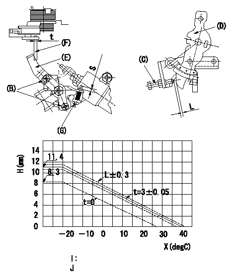
2. Adjustment of the W-FICD
(1)Insert a block gauge L1 determined from the graph below between the control lever (D) and the idling stopper bolt (C).
(2)Insert a shim t between the W-FICD lever (E) and the control lever (F). Adjust the W-FICD lever (E) so that it contacts the control lever (F) and fix it using bolt (B).
TT
Note:
a) The temperature of the wax at the time of adjustment must not exceed d.
b) After completing adjustment, confirm that adjustment allowance of the screw (G) is at least S.
H = control lever dimension L (control lever position)
X = temperature X
I = graph L - X
----------
L1=L+-0.05mm t=3+-0.05mm T=3.4~4.9N-m(0.35~0.5kgf-m) d=30degC S=3mm
----------
t=3mm S=Above 3mm J:L=-0.177X+7.80(-20<=X(degC))(t=3+-0.05)
----------
L1=L+-0.05mm t=3+-0.05mm T=3.4~4.9N-m(0.35~0.5kgf-m) d=30degC S=3mm
----------
t=3mm S=Above 3mm J:L=-0.177X+7.80(-20<=X(degC))(t=3+-0.05)
0000002001 V-FICD ADJUSTMENT
Adjustment of the two stage actuator (FICD).
(C): Stroke adjusting nut
(D): Actuator stroke
(E): Rod position adjusting nut
(F): Stroke adjusting nut
X:Injection quantity
Y:Shim thickness: L
1. Selecting the shim for adjusting the actuator.
(1)Measure the injection quantity at N by inserting the shim L1 between the control lever and the idling stopper bolt.
(2)Select the thickness (L) of the shim for adjusting the actuator using the following formula (refer to the graph.).
Calculation: L
2. Adjustment of the actuator
(1)Mount the actuator to the injection pump.
(2)Position the control lever at the idling position.
(3)Adjust with the nut (D) so that the space between the control lever and the rod becomes L2.
(4)Insert the shim (L) determined above between the control lever and the idling stopper bolt.
(5)Adjust the position of the screw (A) so that the actuator can make its full stroke (Reference value: approx. L3) and fix with the nut (B).
(6)Allowable angle in adjusting the position of the rod: c
----------
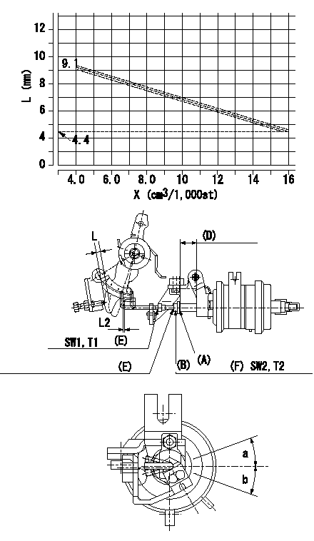
N=900r/min L1=6.2mm L:L+-0.1=-0.39167Q+10.667(4.0<=Q<=16.0cm3/1,000st) L2=1+1mm L3=9.6mm c=+-20deg
----------
L2=1+1mm SW1=SW7 T1=1.4~2.0N-m{0.14~0.2kgf-m} SW2=SW8 T2=3.5~5.0N-m{0.35~0.5kgf-m} a=20deg b=20deg
----------
N=900r/min L1=6.2mm L:L+-0.1=-0.39167Q+10.667(4.0<=Q<=16.0cm3/1,000st) L2=1+1mm L3=9.6mm c=+-20deg
----------
L2=1+1mm SW1=SW7 T1=1.4~2.0N-m{0.14~0.2kgf-m} SW2=SW8 T2=3.5~5.0N-m{0.35~0.5kgf-m} a=20deg b=20deg
Information:
No. 2D diesel fuel is recommended for use in the 1100 Series Caterpillar Diesel Truck Engines, although No. 1D may be used if desired.In selecting a fuel, note that distillate fuels are especially desirable because the fuel is heated to a vaporous state and condensed, thus eliminating all sediment and residue.There is considerable variation in the composition of fuels distributed under the No. 2D grade classifications. For desirable engine service it is most important to give special attention to cetane no., water and sediment, pour point, cloud point and sulphur content. USE FUELS WHICH MEET THE FOLLOWING REQUIREMENTS:Cetane No. ... 40 minimumWater and Sediment ... 0.1% maximumPour Point ... 10F° (-12C°) below ambient temperatureCloud Point ... No higher than ambient temperatureSulphur Content ... Above 0.4% adjust oil change periodGravity ... 32-40 A.P.I. at 60°F (16°C) Cetane No.: This is an indication of a fuel's ignition quality and should not be less than 40 for this engine. For high altitude operation or cold weather starting, a higher cetane number is required. Water and Sediment: A good clean fuel will contain no more than .1% sediment and water. Dirty fuels lead to early filter plugging and in addition can result in the formation or gums and resins reducing filter and engine life. Pour Point: The pour point of the fuel has no effect on engine performance, as long as the fuel is fluid enough to flow from the fuel tank to the engine. The pour point of the fuel should be at least 10F° (-12°C) below the lowest atmospheric temperature at which the engine must start and operate. In extremely cold temperatures it may be necessary to use No. 1D diesel fuel. Cloud Point: Cloud point is the temperature at which wax crystals become visible and is generally above the pour point of the fuel. The cloud point should be no higher than the lowest atmospheric temperature at which the engine must start to keep the fuel filter elements from plugging with wax crystals. Sulphur Content: As sulphur content increases, the crankcase oil change periods should be reduced. Fuel containing 0.4% or less sulphur content, use normal oil change periods. If the fuel contains 0.4% to 1.0% sulphur, oil change periods should be reduced to one-half normal interval. If the fuel contains more than 1.0% sulphur, oil change periods should be reduced to one-fourth normal interval. Gravity: Gravity is the measurement of heat units in a certain amount of fuel. The heavier the fuel (the lower the number) the more heat units per volume. If a fuel with a higher A.P.I. gravity is used the power produced will be lower. Select fuels with the lower A.P.I. gravity reading.Authorized dealers are familiar with fuels that have given good results in Caterpillar Diesel Engines and should be consulted regarding the fuel to use.