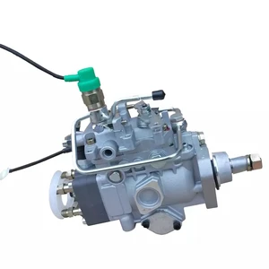
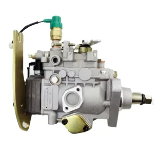
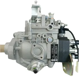
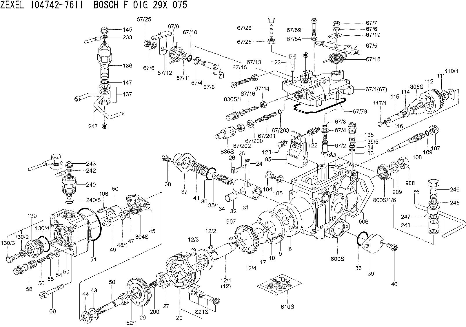
Information injection-pump assembly
BOSCH
F 01G 29X 075
f01g29x075
ZEXEL
104742-7611
1047427611
YANMAR
12991951500
12991951500

Rating:
Compare Prices: .
As an associate, we earn commssions on qualifying purchases through the links below

Fuel Injection Pump Compatible For Yanmar 4TNE98 NP-VE4/12F1150RNP2623 VE 104642-7611 129919-51500 1046427611 12991951500 Engine Parts
SDETASOQ Precise control: precise fuel injection, optimized combustion efficiency, reduced fuel consumption, and improved engine power output || Long lifespan and low maintenance: using high-strength wear-resistant alloy materials and corrosion-resistant coatings to reduce maintenance costs and downtime || Stable operation under all operating conditions: tested in extreme environments, continuously stable, and adaptable to various complex road and climate conditions || Silent and efficient operation: Adopting a noise reduction structure, it can maintain quietness even during high-speed operation, without interfering with the driving experience || Fuel Injection Pump Compatible For Yanmar 4TNE98 NP-VE4/12F1150RNP2623 VE 104642-7611 129919-51500 1046427611 12991951500 Engine Parts
SDETASOQ Precise control: precise fuel injection, optimized combustion efficiency, reduced fuel consumption, and improved engine power output || Long lifespan and low maintenance: using high-strength wear-resistant alloy materials and corrosion-resistant coatings to reduce maintenance costs and downtime || Stable operation under all operating conditions: tested in extreme environments, continuously stable, and adaptable to various complex road and climate conditions || Silent and efficient operation: Adopting a noise reduction structure, it can maintain quietness even during high-speed operation, without interfering with the driving experience || Fuel Injection Pump Compatible For Yanmar 4TNE98 NP-VE4/12F1150RNP2623 VE 104642-7611 129919-51500 1046427611 12991951500 Engine Parts

Fuel Injection Pump Compatible For YANMAR 4TNE98 NP-VE4/12F1150RNP2623 VE 104642-7611 129919-51500 1046427611 12991951500 Engine Parts
Xqscvqwfa Part Number:NP-VE4/12F1150RNP2623 VE 104642-7611 129919-51500 1046427611 12991951500 || Easy Installation:Designed for hassle-free replacement with no modifications required. || Enhanced Durability:Robust construction with high-grade materials for long-lasting reliability. || Improved Fuel Efficiency:Maintains consistent fuel pressure for better combustion and reduced emissions. || Premium Quality:Precision-engineered for optimal fuel pressure and flow, ensuring smooth engine performance.
Xqscvqwfa Part Number:NP-VE4/12F1150RNP2623 VE 104642-7611 129919-51500 1046427611 12991951500 || Easy Installation:Designed for hassle-free replacement with no modifications required. || Enhanced Durability:Robust construction with high-grade materials for long-lasting reliability. || Improved Fuel Efficiency:Maintains consistent fuel pressure for better combustion and reduced emissions. || Premium Quality:Precision-engineered for optimal fuel pressure and flow, ensuring smooth engine performance.

High Pressure Diesel VE Injection Fuel Pump Assembly Compatible For 4TNE 104642-7611 104742-7612 NP-VE4 12F1150RNP2623 129919-51500
Liaeyou Ensures a consistent and stable fuel pressure within the vehicle's fuel system to support optimal engine performance. || Regulates the amount of fuel flowing to the engine according to driving conditions and engine requirements. || Avoids situations where the engine runs out of fuel by continuously supplying an adequate fuel supply. || Collaborates with the fuel injection system to atomize and deliver fuel precisely into the engine cylinders. || By providing the right amount of fuel at the right time, it helps enhance the vehicle's overall fuel efficiency.
Liaeyou Ensures a consistent and stable fuel pressure within the vehicle's fuel system to support optimal engine performance. || Regulates the amount of fuel flowing to the engine according to driving conditions and engine requirements. || Avoids situations where the engine runs out of fuel by continuously supplying an adequate fuel supply. || Collaborates with the fuel injection system to atomize and deliver fuel precisely into the engine cylinders. || By providing the right amount of fuel at the right time, it helps enhance the vehicle's overall fuel efficiency.
You can express buy:
USD 396
19-05-2025
19-05-2025
For YANMAR 4TNE98 Engine Diesel Fuel Injection Pump 104742-7611,129919-51501,104642-7611
USD 411.2
19-05-2025
19-05-2025
104642-7611 104742-7612 NP-VE4/12F1150RNP2623 129919-51500 High Pressure Diesel VE Injection Fuel Pump Assembly for YANMAR 4TNE
USD 442.99
19-05-2025
19-05-2025
104642-7611 104742-7612 NP-VE4/12F1150RNP2623 129919-51500 High Pressure Diesel VE Injection Fuel Pump Assembly For YANMAR 4TNE
Images:
USD 411.32

[13-May-2025]
USD 411.32

[13-May-2025]
USD 411.2

[13-May-2025]
Components :
| 0. | INJECTION-PUMP ASSEMBLY | 104742-7611 |
| 1. | _ | |
| 2. | FUEL INJECTION PUMP | |
| 3. | NUMBER PLATE | |
| 4. | _ | |
| 5. | CAPSULE | |
| 6. | ADJUSTING DEVICE | |
| 7. | NOZZLE AND HOLDER ASSY | 105148-1750 |
| 8. | Nozzle and Holder | |
| 9. | Open Pre:MPa(Kqf/cm2) | 12.3(125) |
| 10. | NOZZLE-HOLDER | 105078-0050 |
| 11. | NOZZLE | 105007-1580 |
Scheme ###:
| 1/6. | [1] | 146601-0700 | PACKING RING |
| 6. | [1] | 146100-0220 | SUPPLY PUMP |
| 9. | [1] | 146103-0100 | COVER |
| 10. | [2] | 139104-0000 | FLAT-HEAD SCREW |
| 12. | [1] | 146200-0320 | DRIVE SHAFT |
| 12/1. | [1] | 146200-0300 | DRIVE SHAFT |
| 12/2. | [1] | 146201-0000 | WOODRUFF KEY |
| 12/3. | [2] | 146202-0100 | DAMPER |
| 12/4. | [1] | 146203-0000 | TOOTHED GEAR |
| 17. | [1] | 146204-0000 | PLAIN WASHER |
| 20. | [1] | 146210-5320 | ROLLER SET |
| 24. | [1] | 146303-0000 | BEARING PIN |
| 25. | [1] | 146304-0000 | BEARING PIN |
| 26. | [1] | 146305-0000 | CLAMPING BAND |
| 27. | [1] | 146205-0000 | SLOTTED WASHER |
| 29. | [1] | 146220-6620 | CAM PLATE |
| 30. | [1] | 146600-0800 | O-RING |
| 31. | [1] | 146311-5820 | PUMP PLUNGER |
| 32. | [1] | 146301-0000 | SLIDING PIECE |
| 34. | [1] | 146312-2200 | COMPRESSION SPRING |
| 35/1. | [1] | 146690-3200 | SHIM D11.5&9.4T0.1 |
| 35/1. | [1] | 146690-3300 | SHIM D11.5&9.4T0.2 |
| 35/1. | [1] | 146690-3400 | SHIM D11.5&9.4T0.25 |
| 35/1. | [1] | 146690-3500 | SHIM D11.5&9.4T1.0 |
| 35/1. | [1] | 146690-4100 | SHIM D11.5&9.4T2 |
| 35/1. | [1] | 146690-4200 | SHIM D11.5&9.4T0.5 |
| 35/1. | [1] | 146690-4300 | SHIM D11.5&9.4T0.75 |
| 36. | [1] | 146600-0800 | O-RING |
| 37. | [1] | 146310-4020 | COVER |
| 38. | [2] | 146620-5000 | BLEEDER SCREW |
| 39. | [1] | 146310-5100 | COVER |
| 40. | [2] | 146620-5000 | BLEEDER SCREW |
| 41. | [1] | 146312-1900 | COMPRESSION SPRING |
| 43. | [1] | 146230-0000 | SHIM |
| 44. | [1] | 146230-0100 | PLAIN WASHER |
| 45. | [1] | 146231-0001 | SLOTTED WASHER |
| 47. | [2] | 146233-0000 | SLOTTED WASHER |
| 48/1. | [1] | 146603-0000 | SHIM D17.0&5.2T0.50 |
| 48/1. | [1] | 146603-0100 | SHIM D17.0&5.2T0.80 |
| 48/1. | [1] | 146603-0200 | SHIM D17.0&5.2T1.00 |
| 48/1. | [1] | 146603-0300 | SHIM D17.0&5.2T1.20 |
| 48/1. | [1] | 146603-0400 | SHIM D17.0&5.2T1.50 |
| 48/1. | [1] | 146603-0500 | SHIM D17.0&5.2T1.80 |
| 48/1. | [1] | 146603-0600 | SHIM D17.0&5.2T2.00 |
| 48/1. | [1] | 146690-1400 | SHIM D17&5.2T0.9 |
| 48/1. | [1] | 146690-1500 | SHIM D17&5.2T1.1 |
| 48/1. | [1] | 146690-1600 | SHIM D17&5.2T1.3 |
| 48/1. | [1] | 146690-1700 | SHIM D17&5.2T1.4 |
| 48/1. | [1] | 146690-1800 | SHIM D17&5.2T1.6 |
| 48/1. | [1] | 146690-1900 | SHIM D17&5.2T1.7 |
| 48/1. | [1] | 146690-5800 | SHIM D17&5.2T2.1 |
| 48/1. | [1] | 146690-5900 | SHIM D17&5.2T2.2 |
| 48/1. | [1] | 146690-6000 | SHIM D17&5.2T2.3 |
| 48/1. | [1] | 146690-6100 | SHIM D17&5.2T2.4 |
| 48/1. | [1] | 146690-6200 | SHIM D17&5.2T2.5 |
| 48/1. | [1] | 146690-6300 | SHIM D17&5.2T2.6 |
| 48/1. | [1] | 146690-6400 | SHIM D17&5.2T2.7 |
| 48/1. | [1] | 146690-6500 | SHIM D17&5.2T2.8 |
| 48/1. | [1] | 146690-6600 | SHIM D17&5.2T2.9 |
| 48/1. | [1] | 146690-6700 | SHIM D17&5.2T3.0 |
| 48/1. | [1] | 146690-6800 | SHIM D17&5.2T3.1 |
| 48/1. | [1] | 146690-6900 | SHIM D17&5.2T3.2 |
| 48/1. | [1] | 146690-7000 | SHIM D17&5.2T3.3 |
| 48/1. | [1] | 146690-7100 | SHIM D17&5.2T3.4 |
| 48/1. | [1] | 146690-7200 | SHIM D17&5.2T0.4 |
| 48/1. | [1] | 146690-7300 | SHIM D17&5.2T0.6 |
| 48/1. | [1] | 146690-7400 | SHIM D17&5.2T0.7 |
| 48/1. | [1] | 146690-7500 | SHIM D17&5.2T1.9 |
| 48/1. | [1] | 146690-7800 | SHIM D17&5.2T0.2 |
| 49. | [2] | 146234-0500 | GUIDE PIN |
| 50. | [1] | 146401-3020 | HYDRAULIC HEAD |
| 50. | [1] | 146401-3020 | HYDRAULIC HEAD |
| 50. | [1] | 146401-3020 | HYDRAULIC HEAD |
| 51. | [1] | 146600-0000 | O-RING |
| 52/1. | [1] | 146420-0000 | SHIM D9.5&3.0T1.90 |
| 52/1. | [1] | 146420-0100 | SHIM D9.5&3.0T1.92 |
| 52/1. | [1] | 146420-0200 | SHIM D9.5&3.0T1.94 |
| 52/1. | [1] | 146420-0300 | SHIM D9.5&3.0T1.96 |
| 52/1. | [1] | 146420-0400 | SHIM D9.5&3.0T1.98 |
| 52/1. | [1] | 146420-0500 | SHIM D9.5&3.0T2.00 |
| 52/1. | [1] | 146420-0600 | SHIM D9.5&3.0T2.02 |
| 52/1. | [1] | 146420-0700 | SHIM D9.5&3.0T2.04 |
| 52/1. | [1] | 146420-0800 | SHIM D9.5&3.0T2.06 |
| 52/1. | [1] | 146420-0900 | SHIM D9.5&3.0T2.08 |
| 52/1. | [1] | 146420-1000 | SHIM D9.5&3.0T2.10 |
| 52/1. | [1] | 146420-1100 | SHIM D9.5&3.0T2.12 |
| 52/1. | [1] | 146420-1200 | SHIM D9.5&3.0T2.14 |
| 52/1. | [1] | 146420-1300 | SHIM D9.5&3.0T2.16 |
| 52/1. | [1] | 146420-1400 | SHIM D9.5&3.0T2.18 |
| 52/1. | [1] | 146420-1500 | SHIM D9.5&3.0T2.20 |
| 52/1. | [1] | 146420-1600 | SHIM D9.5&3.0T2.22 |
| 52/1. | [1] | 146420-1700 | SHIM D9.5&3.0T2.24 |
| 52/1. | [1] | 146420-1800 | SHIM D9.5&3.0T2.26 |
| 52/1. | [1] | 146420-1900 | SHIM D9.5&3.0T2.28 |
| 52/1. | [1] | 146420-2000 | SHIM D9.5&3.0T2.30 |
| 52/1. | [1] | 146420-2100 | SHIM D9.5&3.0T2.32 |
| 52/1. | [1] | 146420-2200 | SHIM D9.5&3.0T2.34 |
| 52/1. | [1] | 146420-2300 | SHIM D9.5&3.0T2.36 |
| 52/1. | [1] | 146420-2400 | SHIM D9.5&3.0T2.38 |
| 52/1. | [1] | 146420-2500 | SHIM D9.5&3.0T2.40 |
| 52/1. | [1] | 146420-2600 | SHIM D9.5&3.0T2.42 |
| 52/1. | [1] | 146420-2700 | SHIM D9.5&3.0T2.44 |
| 52/1. | [1] | 146420-2800 | SHIM D9.5&3.0T2.46 |
| 52/1. | [1] | 146420-2900 | SHIM D9.5&3.0T2.48 |
| 52/1. | [1] | 146420-3000 | SHIM D9.5&3.0T2.50 |
| 52/1. | [1] | 146420-3100 | SHIM D9.5&3.0T2.52 |
| 52/1. | [1] | 146420-3200 | SHIM D9.5&3.0T2.54 |
| 52/1. | [1] | 146420-3300 | SHIM D9.5&3.0T2.56 |
| 52/1. | [1] | 146420-3400 | SHIM D9.5&3.0T2.58 |
| 52/1. | [1] | 146420-3500 | SHIM D9.5&3.0T2.60 |
| 52/1. | [1] | 146420-3600 | SHIM D9.5&3.0T2.62 |
| 52/1. | [1] | 146420-3700 | SHIM D9.5&3.0T2.64 |
| 52/1. | [1] | 146420-3800 | SHIM D9.5&3.0T2.66 |
| 52/1. | [1] | 146420-3900 | SHIM D9.5&3.0T2.68 |
| 52/1. | [1] | 146420-4000 | SHIM D9.5&3.0T2.70 |
| 52/1. | [1] | 146420-4100 | SHIM D9.5&3.0T2.72 |
| 52/1. | [1] | 146420-4200 | SHIM D9.5&3.0T2.74 |
| 52/1. | [1] | 146420-4300 | SHIM D9.5&3.0T2.76 |
| 52/1. | [1] | 146420-4400 | SHIM D9.5&3.0T2.78 |
| 52/1. | [1] | 146420-4500 | SHIM D9.5&3.0T2.80 |
| 52/1. | [1] | 146420-4600 | SHIM D9.5&3.0T2.82 |
| 52/1. | [1] | 146420-4700 | SHIM D9.5&3.0T2.84 |
| 52/1. | [1] | 146420-4800 | SHIM D9.5&3.0T2.86 |
| 52/1. | [1] | 146420-4900 | SHIM D9.5&3.0T2.88 |
| 52/1. | [1] | 146420-5000 | SHIM D9.5&3.0T2.90 |
| 52/1. | [1] | 146420-5100 | SHIM D9.5&3.0T1.74 |
| 52/1. | [1] | 146420-5200 | SHIM D9.5&3.0T1.76 |
| 52/1. | [1] | 146420-5300 | SHIM D9.5&3.0T1.78 |
| 52/1. | [1] | 146420-5400 | SHIM D9.5&3.0T1.80 |
| 52/1. | [1] | 146420-5500 | SHIM D9.5&3.0T1.82 |
| 52/1. | [1] | 146420-5600 | SHIM D9.5&3.0T1.84 |
| 52/1. | [1] | 146420-5700 | SHIM D9.5&3.0T1.86 |
| 52/1. | [1] | 146420-5800 | SHIM D9.5&3.0T1.88 |
| 54. | [4] | 146433-0100 | GASKET |
| 55. | [4] | 146430-3820 | DELIVERY-VALVE ASSEMBLY VE38 |
| 56. | [4] | 146432-0000 | COMPRESSION SPRING |
| 58. | [4] | 146440-0220 | FITTING |
| 60. | [4] | 139106-0100 | FLAT-HEAD SCREW |
| 67. | [1] | 146822-2020 | GOVERNOR COVER |
| 67/1. | [1] | 146805-9320 | GOVERNOR COVER |
| 67/2. | [1] | 146515-0320 | CONTROL SHAFT |
| 67/3. | [1] | 146600-0100 | O-RING |
| 67/4. | [2] | 139310-0200 | PLAIN WASHER |
| 67/4. | [2] | 139310-0200 | PLAIN WASHER |
| 67/5. | [1] | 146833-1500 | CONTROL LEVER |
| 67/5B. | [1] | 146833-1600 | CONTROL LEVER |
| 67/5C. | [1] | 146833-1700 | CONTROL LEVER |
| 67/5D. | [1] | 146833-1800 | CONTROL LEVER |
| 67/6. | [2] | 014110-6440 | LOCKING WASHER D12.2&6.1T1.5 |
| 67/6. | [2] | 014110-6440 | LOCKING WASHER D12.2&6.1T1.5 |
| 67/7. | [1] | 013020-6040 | UNION NUT |
| 67/8. | [1] | 146515-1820 | LEVER SHAFT |
| 67/9. | [1] | 146592-0400 | COILED SPRING |
| 67/10. | [1] | 146600-0200 | O-RING |
| 67/11. | [1] | 146602-0100 | PLAIN WASHER |
| 67/12. | [1] | 146540-4000 | CONTROL LEVER |
| 67/12B. | [1] | 146540-4100 | CONTROL LEVER |
| 67/13. | [1] | 146621-1700 | UNION NUT |
| 67/14. | [1] | 146621-1700 | UNION NUT |
| 67/15. | [1] | 146526-3400 | BLEEDER SCREW |
| 67/16. | [1] | 146526-6400 | BLEEDER SCREW |
| 67/18. | [1] | 146594-1000 | COILED SPRING |
| 67/19. | [1] | 146541-0000 | ANGLE PIECE |
| 67/25. | [2] | 013020-6040 | UNION NUT |
| 67/25. | [2] | 013020-6040 | UNION NUT |
| 67/26. | [1] | 139006-0200 | BLEEDER SCREW |
| 67/64. | [2] | 139306-0400 | PLAIN WASHER |
| 67/69. | [2] | 010206-1040 | HEX-SOCKET-HEAD CAP SCREW |
| 67/78. | [1] | 146600-4400 | SEAL RING |
| 67/200. | [1] | 139308-0300 | PLAIN WASHER |
| 67/201. | [1] | 146545-3400 | THREADED PIN L53.00 |
| 67/201B. | [1] | 146545-3500 | THREADED PIN L55.00 |
| 67/201C. | [1] | 146545-3600 | THREADED PIN L57.00 |
| 67/202. | [1] | 139208-0900 | UNION NUT |
| 67/203. | [1] | 146600-1200 | O-RING |
| 95. | [1] | 146891-0420 | FULCRUM LEVER |
| 104. | [2] | 146568-0000 | SLOTTED SPRING PIN |
| 105. | [2] | 026508-1140 | GASKET D11.4&8.2T1.0 |
| 106. | [2] | 146588-0500 | COILED SPRING |
| 107. | [1] | 146569-0300 | UNION NUT |
| 108. | [1] | 146570-0100 | GOVERNOR SHAFT |
| 109. | [1] | 146600-0400 | O-RING |
| 110/1. | [1] | 146571-0000 | SHIM D20.2&8.3T1.05 |
| 110/1. | [1] | 146571-0100 | SHIM D20.2&8.3T1.25 |
| 110/1. | [1] | 146571-0200 | SHIM D20.2&8.3T1.45 |
| 110/1. | [1] | 146571-0300 | SHIM D20.2&8.3T1.65 |
| 110/1. | [1] | 146571-0400 | SHIM D20.2&8.3T1.85 |
| 110/1. | [1] | 146571-0500 | SHIM D20.2&8.3T1.15 |
| 110/1. | [1] | 146571-0600 | SHIM D20.2&8.3T1.35 |
| 110/1. | [1] | 146571-0700 | SHIM D20.2&8.3T1.55 |
| 110/1. | [1] | 146571-0800 | SHIM D20.2&8.3T1.75 |
| 111. | [1] | 146602-0600 | PLAIN WASHER |
| 112. | [1] | 146572-0020 | FLYWEIGHT ASSEMBLY |
| 114. | [1] | 146602-0500 | PLAIN WASHER |
| 115. | [1] | 146976-3800 | SLIDING SLEEVE |
| 116. | [1] | 146576-0400 | CAP |
| 117/1. | [1] | 146877-0820 | PLUG L=5.0 |
| 117/1. | [1] | 146877-0920 | PLUG L=5.1 |
| 117/1. | [1] | 146877-1020 | PLUG L=5.2 |
| 117/1. | [1] | 146877-1120 | PLUG L=5.3 |
| 117/1. | [1] | 146877-1220 | PLUG L=5.4 |
| 117/1. | [1] | 146877-1320 | PLUG L=5.5 |
| 117/1. | [1] | 146877-1420 | PLUG L=5.6 |
| 117/1. | [1] | 146877-1520 | PLUG L=5.7 |
| 117/1. | [1] | 146877-1620 | PLUG L=5.8 |
| 117/1. | [1] | 146877-1720 | PLUG L=5.9 |
| 117/1. | [1] | 146877-1820 | PLUG L=6.0 |
| 117/1. | [1] | 146877-1920 | PLUG L=6.1 |
| 117/1. | [1] | 146877-2020 | PLUG L=6.2 |
| 117/1. | [1] | 146877-2120 | PLUG L=6.3 |
| 117/1. | [1] | 146877-2220 | PLUG L=6.4 |
| 117/1. | [1] | 146877-2320 | PLUG L=6.5 |
| 117/1. | [1] | 146877-2420 | PLUG L=6.6 |
| 117/1. | [1] | 146877-2520 | PLUG L=6.7 |
| 117/1. | [1] | 146877-2620 | PLUG L=6.8 |
| 117/1. | [1] | 146877-2720 | PLUG L=6.9 |
| 117/1. | [1] | 146877-2820 | PLUG L=7.0 |
| 117/1. | [1] | 146877-2920 | PLUG L=7.1 |
| 117/1. | [1] | 146877-3020 | PLUG L=7.2 |
| 117/1. | [1] | 146877-3120 | PLUG L=7.3 |
| 117/1. | [1] | 146877-3220 | PLUG L=7.4 |
| 117/1. | [1] | 146877-3320 | PLUG L=7.5 |
| 117/1. | [1] | 146877-3420 | PLUG L=7.6 |
| 117/1. | [1] | 146877-3520 | PLUG L=7.7 |
| 117/1. | [1] | 146877-3620 | PLUG L=7.8 |
| 117/1. | [1] | 146877-3720 | PLUG L=7.9 |
| 117/1. | [1] | 146877-3820 | PLUG L=8.0 |
| 117/1. | [1] | 146877-3920 | PLUG L=8.1 |
| 117/1. | [1] | 146877-4020 | PLUG L=8.2 |
| 117/1. | [1] | 146877-4120 | PLUG L=8.3 |
| 117/1. | [1] | 146877-4220 | PLUG L=8.4 |
| 120. | [1] | 146579-9520 | RETAINING PIN |
| 122. | [1] | 146580-3700 | GOVERNOR SPRING |
| 123. | [4] | 139106-0200 | FLAT-HEAD SCREW |
| 130. | [1] | 146421-1020 | CAPSULE |
| 130/2. | [1] | 139508-0200 | GASKET |
| 130/3. | [1] | 146422-0300 | BLEEDER SCREW |
| 130/4. | [1] | 146600-0500 | O-RING |
| 133. | [1] | 146600-0600 | O-RING |
| 134. | [1] | 146600-0700 | O-RING |
| 135. | [1] | 146110-0620 | CONTROL VALVE |
| 135/5. | [1] | 146114-0000 | SPRING WASHER |
| 136. | [1] | 146650-5520 | PULLING ELECTROMAGNET STAMP 55 |
| 137. | [2] | 139514-0200 | GASKET |
| 145. | [1] | 146621-4901 | UNION NUT |
| 147. | [1] | 146600-5000 | O-RING |
| 200. | [1] | 146206-0100 | COILED SPRING |
| 233. | [1] | 146662-9920 | WIRE |
| 240. | [1] | 146650-1220 | PULLING ELECTROMAGNET |
| 240/8. | [1] | 146600-1700 | O-RING |
| 242. | [1] | 146658-4820 | WIRE |
| 243. | [1] | 146621-4901 | UNION NUT |
| 245. | [3] | 139512-0500 | GASKET |
| 246. | [1] | 146125-0600 | EYE BOLT |
| 247. | [1] | 146677-8020 | PIPE |
| 247. | [1] | 146677-8020 | PIPE |
| 248. | [1] | 146614-0200 | SPACER BUSHING |
| 800S. | [1] | 146018-6820 | PUMP HOUSING |
| 800S/1/6. | [1] | 146601-0700 | PACKING RING |
| 804S. | [1] | 146232-0320 | COMPRESSION SPRING |
| 805S. | [1] | 146574-0320 | PARTS SET |
| 810S. | [1] | 146600-1120 | REPAIR SET |
| 821S. | [1] | 146210-5820 | ROLLER SET |
| 835S. | [1] | 146598-1000 | CAP |
| 836S/1. | [1] | 146598-0600 | CAP L18 |
| 836S/1. | [1] | 146598-0700 | CAP L21 |
| 836S/1. | [1] | 146598-0800 | CAP L24 |
| 836S/1. | [1] | 146598-0900 | CAP L27 |
| 906. | [1] | 146911-1400 | NAMEPLATE |
| 907. | [1] | 029470-4030 | WOODRUFF KEY |
| 908. | [1] | 013121-4140 | UNION NUT |
| 909. | [1] | 029321-4050 | LOCKING WASHER |
Include in #2:
104742-7611
as INJECTION-PUMP ASSEMBLY
Cross reference number
BOSCH
F 01G 29X 075
f01g29x075
ZEXEL
104742-7611
1047427611
YANMAR
12991951500
12991951500
Zexel num
Bosch num
Firm num
Name
Calibration Data:
Adjustment conditions
Test oil
1404 Test oil ISO4113orSAEJ967d
1404 Test oil ISO4113orSAEJ967d
Test oil temperature
degC
45
45
50
Nozzle
105780-0060
Bosch type code
NP-DN0SD1510
Nozzle holder
105780-2150
Opening pressure
MPa
13
13
13.3
Opening pressure
kgf/cm2
133
133
136
Injection pipe
157805-7320
Injection pipe
Inside diameter - outside diameter - length (mm) mm 2-6-450
Inside diameter - outside diameter - length (mm) mm 2-6-450
Joint assembly
157641-4720
Tube assembly
157641-4020
Transfer pump pressure
kPa
20
20
20
Transfer pump pressure
kgf/cm2
0.2
0.2
0.2
Direction of rotation (viewed from drive side)
Right R
Right R
(Solenoid timer adjustment condition)
With S/T O-ring; S/T OFF. OFF
With S/T O-ring; S/T OFF. OFF
Injection timing adjustment
Pump speed
r/min
850
850
850
Average injection quantity
mm3/st.
59.8
59.3
60.3
Difference in delivery
mm3/st.
4.5
Basic
*
Oil temperature
degC
50
48
52
Injection timing adjustment_02
Pump speed
r/min
500
500
500
Average injection quantity
mm3/st.
54
48.5
59.5
Oil temperature
degC
48
46
50
Injection timing adjustment_03
Pump speed
r/min
800
800
800
Average injection quantity
mm3/st.
59.8
56.3
63.3
Oil temperature
degC
50
48
52
Injection timing adjustment_04
Pump speed
r/min
850
850
850
Average injection quantity
mm3/st.
59.8
58.8
60.8
Difference in delivery
mm3/st.
5
Basic
*
Oil temperature
degC
50
48
52
Injection timing adjustment_05
Pump speed
r/min
1150
1150
1150
Average injection quantity
mm3/st.
57.2
53.7
60.7
Oil temperature
degC
50
48
52
Injection quantity adjustment
Pump speed
r/min
1313
1313
1313
Average injection quantity
mm3/st.
19.7
15.2
24.2
Difference in delivery
mm3/st.
5
Basic
*
Oil temperature
degC
50
48
52
Injection quantity adjustment_02
Pump speed
r/min
1400
1400
1400
Average injection quantity
mm3/st.
5
Oil temperature
degC
50
48
52
Injection quantity adjustment_03
Pump speed
r/min
1313
1313
1313
Average injection quantity
mm3/st.
19.7
14.7
24.7
Difference in delivery
mm3/st.
5.5
Basic
*
Oil temperature
degC
50
48
52
Governor adjustment
Pump speed
r/min
425
425
425
Average injection quantity
mm3/st.
9.6
7.6
11.6
Difference in delivery
mm3/st.
2
Basic
*
Oil temperature
degC
48
46
50
Governor adjustment_02
Pump speed
r/min
425
425
425
Average injection quantity
mm3/st.
9.6
7.1
12.1
Difference in delivery
mm3/st.
2
Basic
*
Oil temperature
degC
48
46
50
Timer adjustment
Pump speed
r/min
100
100
100
Average injection quantity
mm3/st.
62
57
67
Basic
*
Oil temperature
degC
48
46
50
Remarks
Full
Full
Timer adjustment_02
Pump speed
r/min
100
100
100
Average injection quantity
mm3/st.
62
57
67
Oil temperature
degC
48
46
50
Remarks
Full
Full
Speed control lever angle
Pump speed
r/min
425
425
425
Average injection quantity
mm3/st.
0
0
0
Oil temperature
degC
48
46
50
Remarks
Magnet OFF at idling position
Magnet OFF at idling position
0000000901
Pump speed
r/min
1000
1000
1000
Overflow quantity with S/T ON
cm3/min
480
350
610
Oil temperature
degC
50
48
52
Stop lever angle
Pump speed
r/min
1000
1000
1000
Pressure with S/T ON
kPa
637
598
676
Pressure with S/T ON
kgf/cm2
6.5
6.1
6.9
Pressure with S/T OFF
kPa
539
510
568
Pressure with S/T OFF
kgf/cm2
5.5
5.2
5.8
Basic
*
Oil temperature
degC
50
48
52
Remarks
OFF
OFF
Stop lever angle_02
Pump speed
r/min
1000
1000
1000
Pressure with S/T OFF
kPa
539
500
578
Pressure with S/T OFF
kgf/cm2
5.5
5.1
5.9
Basic
*
Oil temperature
degC
50
48
52
Remarks
OFF
OFF
0000001101
Pump speed
r/min
1000
1000
1000
Timer stroke with S/T ON
mm
3.7
3.2
4.2
Timer stroke with S/T OFF
mm
2.5
2.3
2.7
Basic
*
Oil temperature
degC
50
48
52
Remarks
OFF
OFF
_02
Pump speed
r/min
1000
1000
1000
Timer stroke with S/T ON
mm
3.7
3
4.4
Timer stroke with S/T OFF
mm
2.5
2.1
2.9
Basic
*
Oil temperature
degC
50
48
52
Remarks
OFF
OFF
_03
Pump speed
r/min
1150
1150
1150
Timer stroke with S/T OFF
mm
3.3
2.7
3.9
Oil temperature
degC
50
48
52
0000001201
Max. applied voltage
V
8
8
8
Test voltage
V
13
12
14
Timing setting
K dimension
mm
3.1
3
3.2
KF dimension
mm
5.3
5.2
5.4
MS dimension
mm
1.8
1.7
1.9
Control lever angle alpha
deg.
14
10
18
Control lever angle beta
deg.
27
22
32
Test data Ex:
0000001801 STOP LEVER ADJUSTMENT
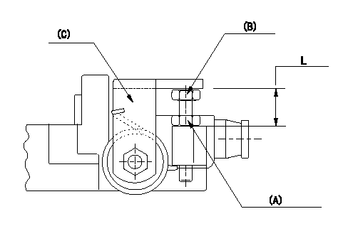
Adjustment of the stop lever
Adjust the bolt (B) so that the starting injection quantity is as specified, then fix using the nut.
(A) Adjusting nut (Torque T)
(B) Adjusting bolt
(C) Starting injection quantity adjusting lever
----------
T=6~9N-m(0.6~0.9kgf-m)
----------
L=15.0~18.5mm
----------
T=6~9N-m(0.6~0.9kgf-m)
----------
L=15.0~18.5mm
Information:
2. Remove three nuts and washers (1).3. Move Peec unit (2) out of the way. (If so equipped). 4. Remove elbows (5) and pipes (7).5. Remove fuel line brackets (4).6. Remove bolts (6). Remove cover (3). 7. Remove elbows (10). Remove adapters (8) and adapters (9) from the aftercooler core. Remove bolts (11). 8. Move aftercooler core (12) toward the front of the engine and use two people to remove the aftercooler core from the lower aftercooler housing. The weight of the aftercooler core is approximately 29 kg (65 lb). Remove the O-ring seals from the aftercooler core extensions.Install Aftercooler
1. Install O-ring seals (13) on the aftercooler core extensions. Put clean engine oil or glycerin on the seals.2. Use two people to put aftercooler core (12) into position in the lower aftercooler housing. The weight of the aftercooler core is approximately 29 kg (65 lb). 3. Install bolts (11). Put clean engine oil or glycerin on O-ring seal (14) and in bores (15) and (16). 4. Put clean engine oil or glycerin on O-ring seals (17) and adapters (8) and (9). Install adapters (8) and (9) in the aftercooler core. 5. Install elbows (10). 6. Put cover (3) into position on the engine. Install bolts (6).7. Install fuel injection line brackets (4). Tighten bolts (20) to a torque of 4.5 1.1 N m (40 10 lb in).8. Put clean engine oil or glycerin on pipes (7). Install pipes (7) and elbows (5).9. Fill the cooling system with coolant. See Operation & Maintenance Manual for the proper procedure and levels.
1. Install O-ring seals (13) on the aftercooler core extensions. Put clean engine oil or glycerin on the seals.2. Use two people to put aftercooler core (12) into position in the lower aftercooler housing. The weight of the aftercooler core is approximately 29 kg (65 lb). 3. Install bolts (11). Put clean engine oil or glycerin on O-ring seal (14) and in bores (15) and (16). 4. Put clean engine oil or glycerin on O-ring seals (17) and adapters (8) and (9). Install adapters (8) and (9) in the aftercooler core. 5. Install elbows (10). 6. Put cover (3) into position on the engine. Install bolts (6).7. Install fuel injection line brackets (4). Tighten bolts (20) to a torque of 4.5 1.1 N m (40 10 lb in).8. Put clean engine oil or glycerin on pipes (7). Install pipes (7) and elbows (5).9. Fill the cooling system with coolant. See Operation & Maintenance Manual for the proper procedure and levels.