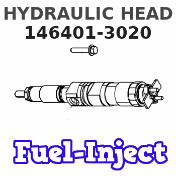
Information hydraulic head
BOSCH
9 461 615 032
9461615032
ZEXEL
146401-3020
1464013020
Rating:
Compare Prices: .
As an associate, we earn commssions on qualifying purchases through the links below

4 - Cylinder 12mm Right - Handed Fuel Injection Pump Parts: Pump Head, Rotor Head (Part# 146401-3020), VE Head Rotor (Part# 9461615032), Spring - Free Design
HNGJOIAIK Accurate fit for 4-cylinder engines: These fuel injection pump parts are designed for 4-cylinder engines with 12mm right-hand drive construction. || SPRINGLESS DESIGN ADVANTAGE: The springless design of these parts reduces the potential points of failure. || CONSTRUCTION: These pump head and rotor parts are made of durable materials to withstand the high pressure requirements of the fuel injection system. || Easy to install: these parts are designed for direct installation, saving time and labor || Fuel Injection Pumps: Ideal for use with fuel injection pumps, these parts are a reliable option for maintaining or upgrading your system
HNGJOIAIK Accurate fit for 4-cylinder engines: These fuel injection pump parts are designed for 4-cylinder engines with 12mm right-hand drive construction. || SPRINGLESS DESIGN ADVANTAGE: The springless design of these parts reduces the potential points of failure. || CONSTRUCTION: These pump head and rotor parts are made of durable materials to withstand the high pressure requirements of the fuel injection system. || Easy to install: these parts are designed for direct installation, saving time and labor || Fuel Injection Pumps: Ideal for use with fuel injection pumps, these parts are a reliable option for maintaining or upgrading your system

$121.93
26 Dec 2024
0.1102[0.05] Pounds
CN: The Mall of the Sea
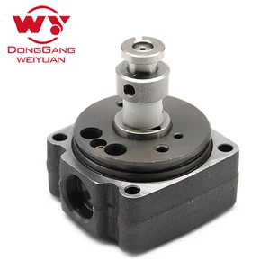
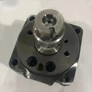
Pump head, rotor head 146401-3020, VE head rotor 9461615032, 4 cylinders / 12mm right, without spring, for fuel injection pump
DIFNWCFE Electric Fuel Pump Function: Suck the fuel from the fuel tank, pressurize it and then deliver it to the fuel supply pipe, and cooperate with the fuel pressure regulator to establish a certain fuel pressure. Guaranteed supply of continuous fuel to the injector. || High Quality Fuel Pump: The automotive replacement electric fuel pumps are manufactured in strict accordance with OEM standards to ensure product quality and longer service life. || The fuel pump, designed as a worn fuel system component, can effectively optimize vehicle performance and fuel efficiency || As an electric motor, the fuel pump achieves optimal power and fuel pressure, thereby accelerating fuel atomization and accelerating start-up speed || Pump head, rotor head 146401-3020, VE head rotor 9461615032, 4 cylinders / 12mm right, without spring, for fuel injection pump
DIFNWCFE Electric Fuel Pump Function: Suck the fuel from the fuel tank, pressurize it and then deliver it to the fuel supply pipe, and cooperate with the fuel pressure regulator to establish a certain fuel pressure. Guaranteed supply of continuous fuel to the injector. || High Quality Fuel Pump: The automotive replacement electric fuel pumps are manufactured in strict accordance with OEM standards to ensure product quality and longer service life. || The fuel pump, designed as a worn fuel system component, can effectively optimize vehicle performance and fuel efficiency || As an electric motor, the fuel pump achieves optimal power and fuel pressure, thereby accelerating fuel atomization and accelerating start-up speed || Pump head, rotor head 146401-3020, VE head rotor 9461615032, 4 cylinders / 12mm right, without spring, for fuel injection pump

Pump Head, Rotor Head 146401-3020, VE Head Rotor 9461615032, 4 Cylinders / 12mm Right, Without Spring, For Fuel Injection Pump
CWEVQBSA High precision fuel injection control: It can control the fuel injection amount extremely accurately based on the real-time operating conditions of the engine, such as speed, load, temperature, and intake air volume, among other factors || Atomize fuel into extremely small and uniform particles, promoting more thorough and perfect mixing of fuel and air in the intake manifold or cylinder || Usually made of materials that are resistant to high temperatures, corrosion, and wear || Through strict precision machining and assembly processes, the dimensional accuracy and fitting accuracy of various components inside the fuel injector are ensured || The injection holes of the fuel injector can ensure that the diameter, shape, and angle of each injection hole are highly consistent, thereby achieving uniform and stable injection effect
CWEVQBSA High precision fuel injection control: It can control the fuel injection amount extremely accurately based on the real-time operating conditions of the engine, such as speed, load, temperature, and intake air volume, among other factors || Atomize fuel into extremely small and uniform particles, promoting more thorough and perfect mixing of fuel and air in the intake manifold or cylinder || Usually made of materials that are resistant to high temperatures, corrosion, and wear || Through strict precision machining and assembly processes, the dimensional accuracy and fitting accuracy of various components inside the fuel injector are ensured || The injection holes of the fuel injector can ensure that the diameter, shape, and angle of each injection hole are highly consistent, thereby achieving uniform and stable injection effect
You can express buy:
USD 58.86
13-05-2025
13-05-2025
146401-3020 Factory price, rotor head 9 461 615 032, 4cry/12R, high quality dissel fuel pump for KOMATSU FORKLIFT 4D95 4D94
USD 73.1
14-06-2025
14-06-2025
146401-3020 diesel pump head rotor for 4/12R jet pump 9461615032
Images:
USD 73.1

[14-Jun-2025]
USD 101.3

[15-Sep-2022]
USD 46.5

[09-Mar-2025]
Include in ###:
Cross reference number
Zexel num
Bosch num
Firm num
Name
146401-3020
9 461 615 032
HYDRAULIC HEAD
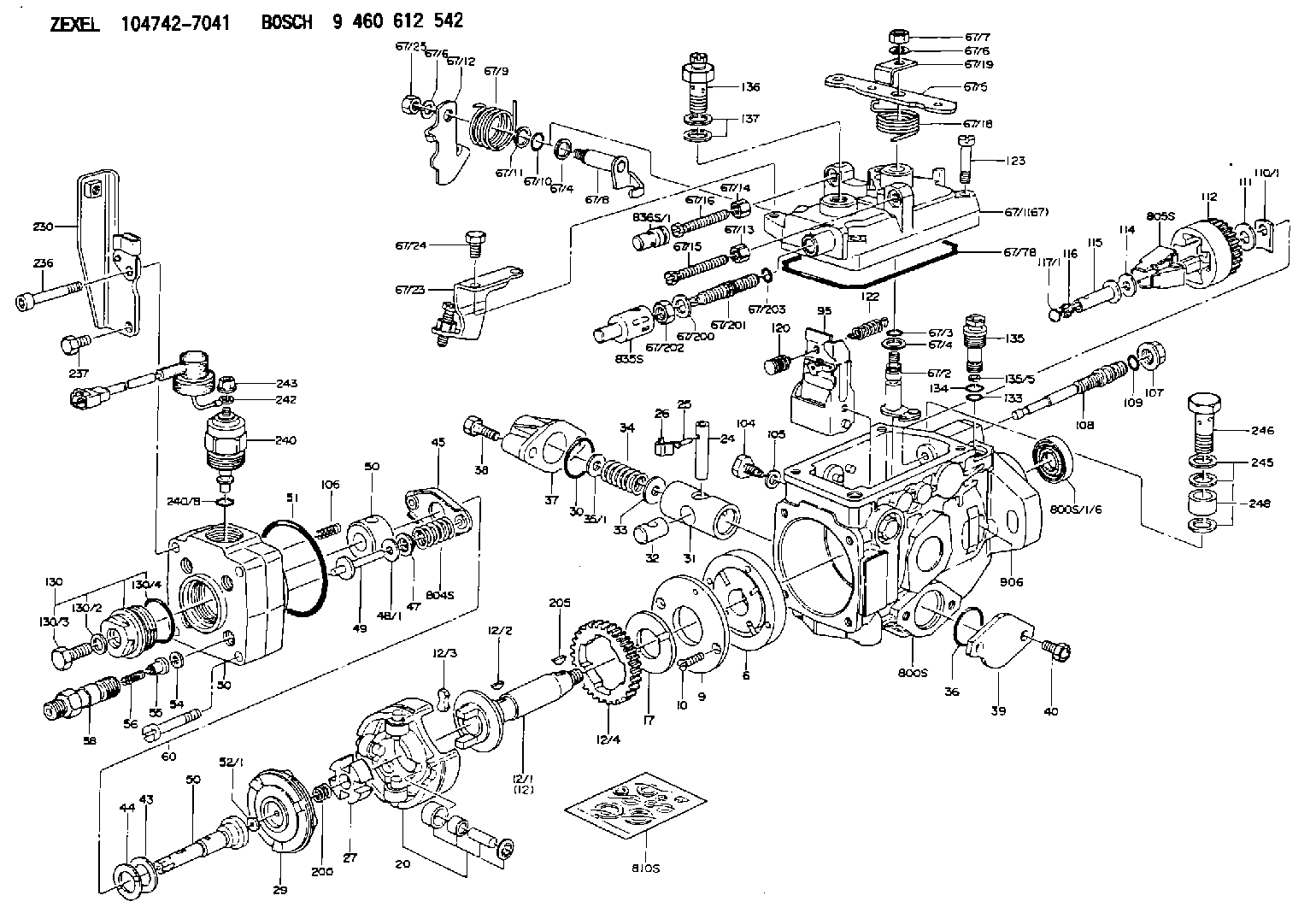
C 11FV DISTRIBUTOR HEAD parts(VE) Others
C 11FV DISTRIBUTOR HEAD parts(VE) Others
Information:
Start By:a. remove oil pump1. Check the main bearing caps for identification for their location and direction in the block. The caps must be installed in the same location and direction from which they were removed. 2. Remove number 2 through number 6 bearing caps (1). Remove thrust plates from the number 4 main bearing.
If the crankshaft is turned in the wrong direction, the tab of the bearing will be pushed between the crankshaft and cylinder block. This can cause damage to either the crankshaft or cylinder block or both.
3. Remove the upper halves of the main bearings by putting Tool (A) in oil hole (2) in the crankshaft. Turn the crankshaft in the direction which will push the end of the bearing with a tab out first.4. Remove the lower halves of the bearings from the caps. Install the bearings dry when the clearance checks are made. Put clean engine oil on the bearings for final assembly.5. Install the new bearings in the caps.6. Install the upper halves of the bearings in the cylinder with Tool (A).
Be sure tabs (3) on the back of the bearings fit in the tab slots of the caps and cylinder block. The serviceman must be very careful to use Plastigage, Tool (B) correctly. The following points must be remembered.
Make sure that the backs of the bearings and the bores are clean and dry.Make sure that the bearing locking tabs are properly seated in their slots.The crankshaft must be free of oil where the Plastigage touches it.If the main bearing clearances are checked with the engine upright or on its side, the crankshaft must be supported. Use a jack under an adjacent crankshaft counterweight and hold the crankshaft against the crown of the bearing. If the crankshaft is not supported, the weight of the crankshaft will cause incorrect readings.Put a piece of Plastigage on the crown of the bearing half that is in the cap. Do not allow the Plastigage to extend over the edge of the bearing.Install the bearing cap using the correct torque-turn specifications. Do not use an impact wrench. Be careful not to dislodge the bearing when the cap is installed.Do not turn the crankshaft with the Plastigage installed.Carefully remove the cap but do not remove the Plastigage. Measure the width of the Plastigage while it is in the bearing cap or on the crankshaft journal. Do this by using the correct scale on the package. Record the measurements.Remove the Plastigage before reinstalling the cap.When using Plastigage, the readings can sometimes be unclear. For example, all parts of the Plastigage are not the same width. Measure the major widths to make sure that they are within the specification range. Also, experience has shown that when checking clearances tighter than 0.10 mm (.004 in) the readings may be low by 0.013 to 0.025 mm (.0005 to .0010 in). Out-of-round journals can give faulty readings. Also, journal taper may be indicated when one end of the Plastigage is wider that the
Have questions with 146401-3020?
Group cross 146401-3020 ZEXEL
146401-3020
9 461 615 032
HYDRAULIC HEAD