Information injection-pump assembly
BOSCH
9 400 612 804
9400612804
ZEXEL
101609-9181
1016099181
MITSUBISHI-HEAV
3436106040
3436106040
Rating:
Service parts 101609-9181 INJECTION-PUMP ASSEMBLY:
1.
_

5.
AUTOM. ADVANCE MECHANIS
6.
COUPLING PLATE
7.
COUPLING PLATE
8.
_
9.
_
11.
Nozzle and Holder
12.
Open Pre:MPa(Kqf/cm2)
21.6{220}

15.
NOZZLE SET
Include in #1:
101609-9181
as INJECTION-PUMP ASSEMBLY
Include in #2:
104015-8170
as _
Cross reference number
BOSCH
9 400 612 804
9400612804
ZEXEL
101609-9181
1016099181
MITSUBISHI-HEAV
3436106040
3436106040
Zexel num
Bosch num
Firm num
Name
101609-9181
9 400 612 804
3436106040 MITSUBISHI-HEAV
INJECTION-PUMP ASSEMBLY
S6K-T K 14BF INJECTION PUMP ASSY PE6AD PE
S6K-T K 14BF INJECTION PUMP ASSY PE6AD PE
Calibration Data:
Adjustment conditions
Test oil
1404 Test oil ISO4113 or {SAEJ967d}
1404 Test oil ISO4113 or {SAEJ967d}
Test oil temperature
degC
40
40
45
Nozzle and nozzle holder
105780-8140
Bosch type code
EF8511/9A
Nozzle
105780-0000
Bosch type code
DN12SD12T
Nozzle holder
105780-2080
Bosch type code
EF8511/9
Opening pressure
MPa
17.2
Opening pressure
kgf/cm2
175
Injection pipe
Outer diameter - inner diameter - length (mm) mm 6-2-600
Outer diameter - inner diameter - length (mm) mm 6-2-600
Overflow valve
131424-5720
Overflow valve opening pressure
kPa
255
255
255
Overflow valve opening pressure
kgf/cm2
2.6
2.6
2.6
Tester oil delivery pressure
kPa
255
255
255
Tester oil delivery pressure
kgf/cm2
2.6
2.6
2.6
Direction of rotation (viewed from drive side)
Right R
Right R
Injection timing adjustment
Direction of rotation (viewed from drive side)
Right R
Right R
Injection order
1-5-3-6-
2-4
Pre-stroke
mm
3.2
3.15
3.25
Beginning of injection position
Drive side NO.1
Drive side NO.1
Difference between angles 1
Cal 1-5 deg. 60 59.5 60.5
Cal 1-5 deg. 60 59.5 60.5
Difference between angles 2
Cal 1-3 deg. 120 119.5 120.5
Cal 1-3 deg. 120 119.5 120.5
Difference between angles 3
Cal 1-6 deg. 180 179.5 180.5
Cal 1-6 deg. 180 179.5 180.5
Difference between angles 4
Cyl.1-2 deg. 240 239.5 240.5
Cyl.1-2 deg. 240 239.5 240.5
Difference between angles 5
Cal 1-4 deg. 300 299.5 300.5
Cal 1-4 deg. 300 299.5 300.5
Injection quantity adjustment
Adjusting point
A
Rack position
9.6
Pump speed
r/min
900
900
900
Average injection quantity
mm3/st.
103
102
104
Max. variation between cylinders
%
0
-2.5
2.5
Basic
*
Fixing the lever
*
Injection quantity adjustment_02
Adjusting point
-
Rack position
6.6+-0.5
Pump speed
r/min
450
450
450
Average injection quantity
mm3/st.
12
10.7
13.3
Max. variation between cylinders
%
0
-14
14
Fixing the rack
*
Remarks
Adjust only variation between cylinders; adjust governor according to governor specifications.
Adjust only variation between cylinders; adjust governor according to governor specifications.
Injection quantity adjustment_03
Adjusting point
E
Rack position
9.8++
Pump speed
r/min
100
100
100
Average injection quantity
mm3/st.
65
65
70
Fixing the lever
*
Rack limit
*
Test data Ex:
Governor adjustment
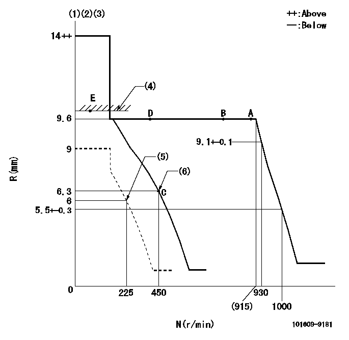
N:Pump speed
R:Rack position (mm)
(1)Target notch: K
(2)Tolerance for racks not indicated: +-0.05mm.
(3)Negative torque control does not operate
(4)RACK LIMIT
(5)Set idle sub-spring
(6)Main spring setting
----------
K=9
----------
----------
K=9
----------
Speed control lever angle
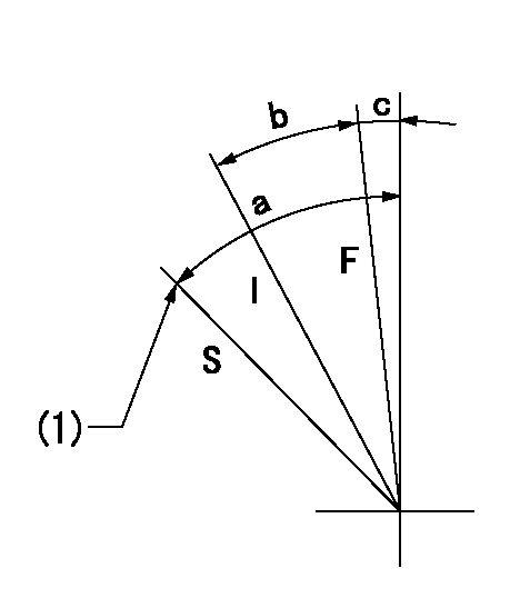
F:Full speed
I:Idle
S:Stop
(1)Stopper bolt setting
----------
----------
a=31deg+-3deg b=14deg+-5deg c=3deg+-5deg
----------
----------
a=31deg+-3deg b=14deg+-5deg c=3deg+-5deg
Stop lever angle
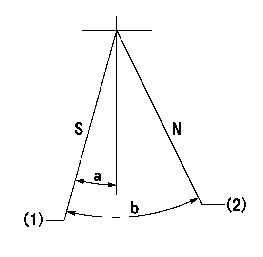
N:Pump normal
S:Stop the pump.
(1)Rack position = aa, speed = bb.
(2)Normal
----------
aa=1-0.5mm bb=0r/min
----------
a=21deg+-5deg b=(55deg)
----------
aa=1-0.5mm bb=0r/min
----------
a=21deg+-5deg b=(55deg)
Timing setting

(1)Pump vertical direction
(2)Position of camshaft's key groove at No 1 cylinder's beginning of injection
(3)-
(4)-
----------
----------
a=(50deg)
----------
----------
a=(50deg)
Information:
Before any service work is to be done on this fuel system, the outer surface of the injection pump housing must be clean.
The fuel injection pump housing and governor has been removed from the engine for illustration purposes. 1. Remove the flange (1) and the flange assembly from the cover.2. Remove the cover (2) from the pump housing. 3. Remove the bypass valve (3) and springs from the pump housing. 4. Install tooling (A) on the fuel injection pump and loosen the bushing from the pump housing. Do not loosen the screws (4) that hold the levers to the shaft when removing or installing pumps. If the levers are moved, fuel pump calibration will be changed. 5. Remove the fuel injection pump (5) from the pump housing. The sleeve (6) on the plunger will slide off the lever as the pump is removed.6. Do Steps 4 and 5 for the remainder of the pumps.Install Fuel Injection Pumps
1. Turn the camshaft until the lifter for the pump to be installed is at its lowest position. 2. Install the fuel injection pump (1) in the bore of the pump housing.3. The sleeve (2) will be engaged with the lever when the pump is installed correctly.
If the levers have been moved on the shaft, fuel pump calibration must be made. (See Testing and Adjusting).
4. Tighten the bushing with tooling (A) to a torque of 70 5 lb.ft. (9.7 0.7 mkg).5. Do Steps 1 through 4 for the remainder of the pumps. 6. Install the bypass valve and spring (3) in the pump housing. 7. Install the cover (5) on the pump housing. Be sure the spring (3) is in the bore in the cover.8. Install the flange (4) and the flange assembly on the cover.Disassemble Fuel Injection Pumps
start by: a) remove fuel injection pumps 1. Remove the bushing (1) and seal from the bonnet (2).2. Remove the ring (3) from the bonnet and barrel (7). Remove the check valve (6) and spring (4) from the bonnet.3. Remove the spring (8) and washer (5). Remove the plunger (9) and sleeve (10). Keep the plunger and sleeve with their respective barrel for installation. Do not use plungers, sleeves and barrels with other plungers, sleeves and barrels.Assemble Fuel Injection Pumps
1. Install the sleeve (4), plunger (5), spring (2) and washer (3) on the barrel (1). Be sure the sleeve and plunger are installed in their original barrel and the large hole in the plunger is up. The sleeve must be installed with the thin flange up.2. Install the check valve and spring in the bonnet. Connect the barrel and bonnet and install the ring. Install the seal and bushing on the bonnet.end by: a) install fuel injection pumps
Have questions with 101609-9181?
Group cross 101609-9181 ZEXEL
Dpico
Mitsubishi-Heav
Dpico
Mitsubishi-Heav
Mitsubishi-Heav
Mitsubishi-Heav
101609-9181
9 400 612 804
3436106040
INJECTION-PUMP ASSEMBLY
S6K-T
S6K-T