Information injection-pump assembly
BOSCH
F 01G 0V0 001
f01g0v0001
ZEXEL
101609-3640
1016093640
KOMATSU
4063209
4063209

Rating:
Compare Prices: .
As an associate, we earn commssions on qualifying purchases through the links below

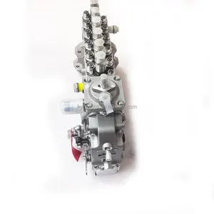
Fuel Injection Pump 101609-3640 1016093640 Suitable for Komatsu 6D102 Engine PC200-7 PC220-7
OfkZynodor Product name:Fuel Injection Pump || Part Number:101609-3640 1016093640 || APPlication:Suitable for Komatsu 6D102 Engine PC200-7 PC220-7 || Please make sure to carefully compare the photos and check the part numbers before making the purchase. If you are unable to confirm your engine model or part number, please leave us a message and we will assist you in confirming that the product you purchase is the one you need. || Your order is not merely a single purchase but the beginning of a cooperative journey, aiming to ensure the safe and smooth operation of your vehicle. We are proud to offer you reliable precision engineering components and unparalleled services.
OfkZynodor Product name:Fuel Injection Pump || Part Number:101609-3640 1016093640 || APPlication:Suitable for Komatsu 6D102 Engine PC200-7 PC220-7 || Please make sure to carefully compare the photos and check the part numbers before making the purchase. If you are unable to confirm your engine model or part number, please leave us a message and we will assist you in confirming that the product you purchase is the one you need. || Your order is not merely a single purchase but the beginning of a cooperative journey, aiming to ensure the safe and smooth operation of your vehicle. We are proud to offer you reliable precision engineering components and unparalleled services.

Fuel Injection Pump 101609-3640 1016093640 For Komatsu 6D102 Engine PC200-7 PC220-7
oiasdfhjdg Product name:Fuel Injection Pump || Part Number:101609-3640 1016093640 || APPlication:For Komatsu 6D102 Engine PC200-7 PC220-7 || 1.Please carefully compare the OE numbers before purchasing the product to match your original parts and avoid wasting your valuable time. || 2.Please ensure to provide us with the correct, accurate, and detailed delivery address and contact information
oiasdfhjdg Product name:Fuel Injection Pump || Part Number:101609-3640 1016093640 || APPlication:For Komatsu 6D102 Engine PC200-7 PC220-7 || 1.Please carefully compare the OE numbers before purchasing the product to match your original parts and avoid wasting your valuable time. || 2.Please ensure to provide us with the correct, accurate, and detailed delivery address and contact information
Fuel Injection Pump 101609-3640 1016093640 Suitable for Komatsu 6D102 Engine PC200-7 PC220-7
TuneCrumph 🚕Product name:Fuel Injection Pump || 🚕Part Number:101609-3640 1016093640 || 🚕APPlication:Suitable for Komatsu 6D102 Engine PC200-7 PC220-7 || 🚕Attention: Dear buyers, precise matching of auto parts is the prerequisite for safe installation! To avoid the problems such as returns, exchanges or installation hazards caused by incorrect model selection, please carefully read and verify the model before placing your order. Thank you for your support! || 🚕NOTE:We are fully aware that your satisfaction is the driving force for the growth of our brand. Thank you for giving us the opportunity to serve you. If there is anything we haven't covered, please give us your feedback directly. Your suggestions are extremely precious to us!
TuneCrumph 🚕Product name:Fuel Injection Pump || 🚕Part Number:101609-3640 1016093640 || 🚕APPlication:Suitable for Komatsu 6D102 Engine PC200-7 PC220-7 || 🚕Attention: Dear buyers, precise matching of auto parts is the prerequisite for safe installation! To avoid the problems such as returns, exchanges or installation hazards caused by incorrect model selection, please carefully read and verify the model before placing your order. Thank you for your support! || 🚕NOTE:We are fully aware that your satisfaction is the driving force for the growth of our brand. Thank you for giving us the opportunity to serve you. If there is anything we haven't covered, please give us your feedback directly. Your suggestions are extremely precious to us!
You can express buy:
USD 3131.13
28-06-2025
28-06-2025
Engine Parts 6BT5.9 Injection Pump 4063845 4063208 4063209 Fuel Injection Pump 6738-71-1520 101609-3750 1016093750
US $1710.00
24-12-2016
24-12-2016
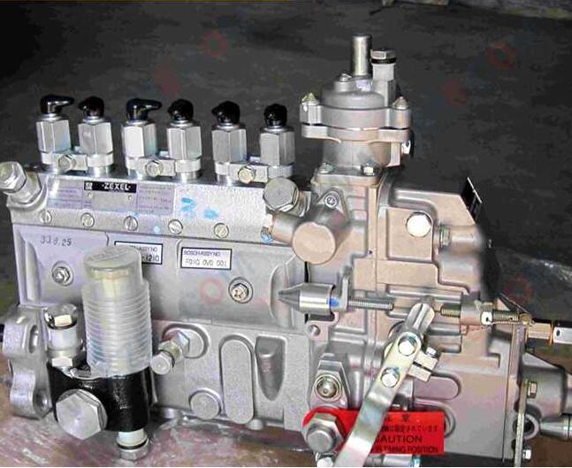
Genuine PE fuel injection pump 101609-3640, F01G0V0001 for KOM/ATSU PC220-7 6738-71-1210, 6738711210
Images:
US $1685.00

[22-Dec-2016]
USD 1800

[08-Mar-2017]
Service parts 101609-3640 INJECTION-PUMP ASSEMBLY:
1.
_


5.
AUTOM. ADVANCE MECHANIS
6.
COUPLING PLATE
7.
COUPLING PLATE
8.
_
9.
_
11.
Nozzle and Holder
4063212
12.
Open Pre:MPa(Kqf/cm2)
22.0{224}

15.
NOZZLE SET
Include in #1:
101609-3640
as INJECTION-PUMP ASSEMBLY
Cross reference number
BOSCH
F 01G 0V0 001
f01g0v0001
ZEXEL
101609-3640
1016093640
KOMATSU
4063209
4063209
Zexel num
Bosch num
Firm num
Name
101609-3640
F 01G 0V0 001
4063209 KOMATSU
INJECTION-PUMP ASSEMBLY
6BTAA K 14BE INJECTION PUMP ASSY PE6A PE
6BTAA K 14BE INJECTION PUMP ASSY PE6A PE
101609-3640
F 01G 0V0 001
6738711210 KOMATSU
INJECTION-PUMP ASSEMBLY
6BTAA K 14BE INJECTION PUMP ASSY PE6A PE
6BTAA K 14BE INJECTION PUMP ASSY PE6A PE
Calibration Data:
Adjustment conditions
Test oil
1404 Test oil ISO4113 or {SAEJ967d}
1404 Test oil ISO4113 or {SAEJ967d}
Test oil temperature
degC
40
40
45
Nozzle and nozzle holder
105780-8140
Bosch type code
EF8511/9A
Nozzle
105780-0000
Bosch type code
DN12SD12T
Nozzle holder
105780-2080
Bosch type code
EF8511/9
Opening pressure
MPa
17.2
Opening pressure
kgf/cm2
175
Injection pipe
Outer diameter - inner diameter - length (mm) mm 6-2-600
Outer diameter - inner diameter - length (mm) mm 6-2-600
Overflow valve
131424-3420
Overflow valve opening pressure
kPa
255
221
289
Overflow valve opening pressure
kgf/cm2
2.6
2.25
2.95
Tester oil delivery pressure
kPa
255
255
255
Tester oil delivery pressure
kgf/cm2
2.6
2.6
2.6
Direction of rotation (viewed from drive side)
Right R
Right R
Injection timing adjustment
Direction of rotation (viewed from drive side)
Right R
Right R
Injection order
1-5-3-6-
2-4
Pre-stroke
mm
2.6
2.55
2.65
Rack position
After adjusting injection quantity. R=A
After adjusting injection quantity. R=A
Beginning of injection position
Drive side NO.1
Drive side NO.1
Difference between angles 1
Cal 1-5 deg. 60 59.5 60.5
Cal 1-5 deg. 60 59.5 60.5
Difference between angles 2
Cal 1-3 deg. 120 119.5 120.5
Cal 1-3 deg. 120 119.5 120.5
Difference between angles 3
Cal 1-6 deg. 180 179.5 180.5
Cal 1-6 deg. 180 179.5 180.5
Difference between angles 4
Cyl.1-2 deg. 240 239.5 240.5
Cyl.1-2 deg. 240 239.5 240.5
Difference between angles 5
Cal 1-4 deg. 300 299.5 300.5
Cal 1-4 deg. 300 299.5 300.5
Injection quantity adjustment
Adjusting point
A
Rack position
12
Pump speed
r/min
1000
1000
1000
Average injection quantity
mm3/st.
128.5
127.5
129.5
Max. variation between cylinders
%
0
-2.5
2.5
Basic
*
Fixing the lever
*
Boost pressure
kPa
53.3
53.3
Boost pressure
mmHg
400
400
Injection quantity adjustment_02
Adjusting point
-
Rack position
7.8+-0.5
Pump speed
r/min
525
525
525
Average injection quantity
mm3/st.
9.5
8.5
10.5
Max. variation between cylinders
%
0
-15
15
Fixing the rack
*
Boost pressure
kPa
0
0
0
Boost pressure
mmHg
0
0
0
Remarks
Adjust only variation between cylinders; adjust governor according to governor specifications.
Adjust only variation between cylinders; adjust governor according to governor specifications.
Injection quantity adjustment_03
Adjusting point
D
Rack position
10.3
Pump speed
r/min
100
100
100
Average injection quantity
mm3/st.
50
45
55
Fixing the lever
*
Boost pressure
kPa
0
0
0
Boost pressure
mmHg
0
0
0
Injection quantity adjustment_04
Adjusting point
E
Rack position
12.2++
Pump speed
r/min
100
100
100
Average injection quantity
mm3/st.
120
115
125
Fixing the lever
*
Boost pressure
kPa
53.3
53.3
Boost pressure
mmHg
400
400
Rack limit
*
Boost compensator adjustment
Pump speed
r/min
850
850
850
Rack position
10.3
Boost pressure
kPa
29.3
26.6
32
Boost pressure
mmHg
220
200
240
Boost compensator adjustment_02
Pump speed
r/min
850
850
850
Rack position
R1(12)
Boost pressure
kPa
40
40
40
Boost pressure
mmHg
300
300
300
Test data Ex:
Governor adjustment
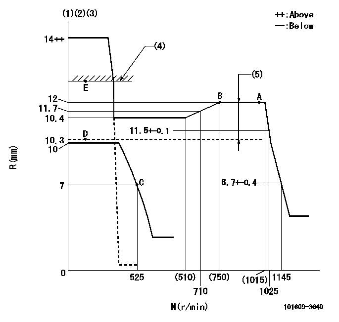
N:Pump speed
R:Rack position (mm)
(1)Target notch: K
(2)Tolerance for racks not indicated: +-0.05mm.
(3)It is not necessary to supply hydraulic pressure because the specification is for the hydraulic ACT normally ON.
(4)RACK LIMIT
(5)Boost compensator stroke: BCL
----------
K=12 BCL=(1.7)mm
----------
----------
K=12 BCL=(1.7)mm
----------
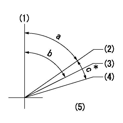
Speed control lever angle
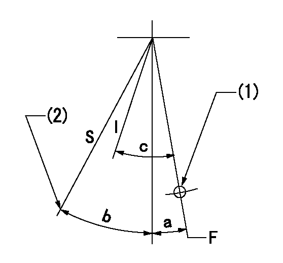
F:Full speed
I:Idle
S:Stop
(1)Use hole at R = aa (middle hole)
(2)Stopper bolt setting
----------
aa=77mm
----------
a=7deg+-5deg b=31deg+-3deg c=28deg+-5deg
----------
aa=77mm
----------
a=7deg+-5deg b=31deg+-3deg c=28deg+-5deg
0000001501 TAMPER PROOF
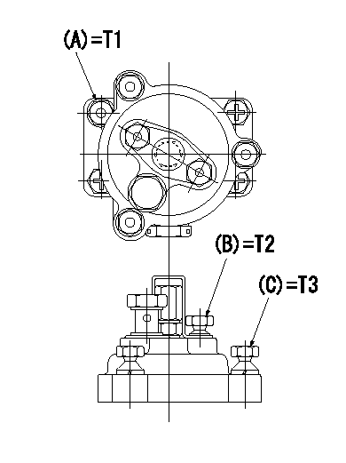
Tamperproofing-equipped boost compensator cover installation procedure
(1)After adjusting the governor and the boost compensator, tighten to the specified torque to break off the bolt heads.
(Tightening torque T = T1 maximum)
(2)After adjusting the governor and the boost compensator, tighten to the specified torque to break off the bolt heads.
(Tightening torque T = T2)
(3)After adjusting the governor and the boost compensator, tighten to the specified torque to break off the bolt heads.
(Tightening torque T = T3)
----------
T1=7.16~9.12N-m(0.73~0.93kgf-m) T2=2.9~4.4N-m(0.3~0.45kgf-m) T3=2.9~4.4N-m(0.3~0.45kgf-m)
----------
----------
T1=7.16~9.12N-m(0.73~0.93kgf-m) T2=2.9~4.4N-m(0.3~0.45kgf-m) T3=2.9~4.4N-m(0.3~0.45kgf-m)
----------
0000001601 I/P WITH LOAD PLUNGER ADJ
Adjusting procedure for load plunger equipped pump with RSV (cam lock) governor (see service information S.I. 434 for details).
At cam lift h+-0.01, set the camshaft c deg from the * mark in accordance with the timing adjustment procedure.
2. Align the flyweight's timing tooth position and the lock pin groove and then fully tighten the flyweight to the camshaft. Then, remove the lock pin.
3. Adjust the maximum variation between cylinders and injection quantity.
4. Adjust using the pre-stroke adjusting shim so that the pre-stroke value is the value for 4/4 load (standard point A).
5. After adjusting the pre-stroke, reconfirm that the injection quantity and the maximum variation between cylinders are as specified.
6. At delivery, again fix the flyweight using the lock pin.
----------
h=2.6mm c=5deg30min+-30min
----------
----------
h=2.6mm c=5deg30min+-30min
----------
Timing setting
(1)Pump vertical direction
(2)Key groove position for No. 1 cylinder's cam lift h = cc (at BTDC aa).
(3)Key groove position for No. 1 cylinder's beginning of injection (at point A after injection quantity adjustment).
(4)Position of the key groove of the No. 1 cylinder at B.T.D.C. bb (fix the governor flyweight at this position for delivery).
(5)B.T.D.C.: aa
----------
aa=11deg bb=0deg cc=2.6+-0.1mm
----------
a=55deg18min+-3deg b=55deg18min+-3deg13min48sec c=5deg30min+-30min
----------
aa=11deg bb=0deg cc=2.6+-0.1mm
----------
a=55deg18min+-3deg b=55deg18min+-3deg13min48sec c=5deg30min+-30min
Information:
Start By:a. remove fuel injection lines 1. Remove bolt (1) and clamp (2) from the fuel injection nozzles to be removed.2. Install Tool (A) with the inside lip of the puller on the lower stepped diameter of the nozzle and the tip of the button in the threaded hole for bolt (1).
Do not exceed a torque of 17 N m (150 lb in) on the screw of Tool (A) during removal of the nozzle. Added force can cause the stem of the nozzle to bend or break off.
3. Tighten the screw of Tool (A) to a maximum torque of 17 N m (150 lb in) to remove fuel injection nozzle (3).4. If the fuel injection nozzle can not be removed with a maximum torque of 17 N m (150 lb in) on the screw of Tool (A), remove Tool (A).
Typical Example5. Remove the protective cap from fuel injection nozzle (3), and install Tool (B) as shown.
Hold Tool (B) so the center line of the tool is in alignment with the centerline of fuel injection nozzle (3). This will prevent distortion of the nozzle which can cause it to bend or break off during removal.
6. Remove the fuel injection nozzle with Tool (B).7. If Tool (B) was used to remove the fuel injection nozzle, replace the nozzle.8. If Tool (A) was used to remove the fuel injection nozzle, remove the carbon dam seal on the end of the nozzle.Install Fuel Injection Nozzle
1. Use Tool (C) to clean the bore for the fuel injection nozzle. Use an open end wrench or tap driver to turn Tool (C).2. Make reference to Special Instruction, Form No. SEHS7292, for the use of Tool (D). Clean the fuel injection nozzle with Tool (D). 3. Install a new seal (4) on fuel injection nozzle (3).4. Put carbon dam seal (5) on the small end of Tool (E). Expand the carbon dam seal by sliding it to the large end. Put Tool (E) against the fuel injection nozzle. Slide carbon dam seal (5) off Tool (E) on to the nozzle. Slide the carbon dam seal into position in the groove on the nozzle as shown. 5. Put fuel injection nozzle (3) in position in the cylinder head. Install clamp (2) and bolt (1) to hold the nozzle in position.End By:a. install fuel injection lines
Have questions with 101609-3640?
Group cross 101609-3640 ZEXEL
Komatsu
Komatsu
Komatsu
101609-3640
F 01G 0V0 001
4063209
INJECTION-PUMP ASSEMBLY
6BTAA
6BTAA
101609-3640
F 01G 0V0 001
6738711210
INJECTION-PUMP ASSEMBLY
6BTAA
6BTAA