Information injection-pump assembly
BOSCH
9 400 615 907
9400615907
ZEXEL
101609-3470
1016093470
KOMATSU
3863834
3863834
Rating:
Service parts 101609-3470 INJECTION-PUMP ASSEMBLY:
1.
_
5.
AUTOM. ADVANCE MECHANIS
6.
COUPLING PLATE
7.
COUPLING PLATE
8.
_
9.
_
10.
NOZZLE AND HOLDER ASSY
11.
Nozzle and Holder
12.
Open Pre:MPa(Kqf/cm2)
13.
NOZZLE-HOLDER
14.
NOZZLE
15.
NOZZLE SET
Include in #1:
101609-3470
as INJECTION-PUMP ASSEMBLY
Include in #2:
104058-3390
as _
Cross reference number
BOSCH
9 400 615 907
9400615907
ZEXEL
101609-3470
1016093470
KOMATSU
3863834
3863834
Zexel num
Bosch num
Firm num
Name
101609-3470
9 400 615 907
3863834 KOMATSU
INJECTION-PUMP ASSEMBLY
S6D102E K 14BE INJECTION PUMP ASSY PE6A PE
S6D102E K 14BE INJECTION PUMP ASSY PE6A PE
101609-3470
9 400 615 907
6735711440 KOMATSU
INJECTION-PUMP ASSEMBLY
S6D102E K 14BE INJECTION PUMP ASSY PE6A PE
S6D102E K 14BE INJECTION PUMP ASSY PE6A PE
Calibration Data:
Adjustment conditions
Test oil
1404 Test oil ISO4113 or {SAEJ967d}
1404 Test oil ISO4113 or {SAEJ967d}
Test oil temperature
degC
40
40
45
Nozzle and nozzle holder
105780-8140
Bosch type code
EF8511/9A
Nozzle
105780-0000
Bosch type code
DN12SD12T
Nozzle holder
105780-2080
Bosch type code
EF8511/9
Opening pressure
MPa
17.2
Opening pressure
kgf/cm2
175
Injection pipe
Outer diameter - inner diameter - length (mm) mm 6-2-600
Outer diameter - inner diameter - length (mm) mm 6-2-600
Overflow valve
131424-3420
Overflow valve opening pressure
kPa
255
221
289
Overflow valve opening pressure
kgf/cm2
2.6
2.25
2.95
Tester oil delivery pressure
kPa
157
157
157
Tester oil delivery pressure
kgf/cm2
1.6
1.6
1.6
Direction of rotation (viewed from drive side)
Right R
Right R
Injection timing adjustment
Direction of rotation (viewed from drive side)
Right R
Right R
Injection order
1-5-3-6-
2-4
Pre-stroke
mm
2.5
2.45
2.55
Beginning of injection position
Drive side NO.1
Drive side NO.1
Difference between angles 1
Cal 1-5 deg. 60 59.5 60.5
Cal 1-5 deg. 60 59.5 60.5
Difference between angles 2
Cal 1-3 deg. 120 119.5 120.5
Cal 1-3 deg. 120 119.5 120.5
Difference between angles 3
Cal 1-6 deg. 180 179.5 180.5
Cal 1-6 deg. 180 179.5 180.5
Difference between angles 4
Cyl.1-2 deg. 240 239.5 240.5
Cyl.1-2 deg. 240 239.5 240.5
Difference between angles 5
Cal 1-4 deg. 300 299.5 300.5
Cal 1-4 deg. 300 299.5 300.5
Injection quantity adjustment
Adjusting point
A
Rack position
9.7
Pump speed
r/min
1000
1000
1000
Average injection quantity
mm3/st.
92
91
93
Max. variation between cylinders
%
0
-2.5
2.5
Basic
*
Fixing the lever
*
Boost pressure
kPa
49.3
49.3
Boost pressure
mmHg
370
370
Hydraulic cylinder ON
*
Injection quantity adjustment_02
Adjusting point
C
Rack position
7+-0.5
Pump speed
r/min
500
500
500
Average injection quantity
mm3/st.
13
12
14
Max. variation between cylinders
%
0
-15
15
Fixing the rack
*
Boost pressure
kPa
0
0
0
Boost pressure
mmHg
0
0
0
Hydraulic cylinder ON
*
Injection quantity adjustment_03
Adjusting point
D
Rack position
-
Pump speed
r/min
100
100
100
Average injection quantity
mm3/st.
70
70
80
Fixing the lever
*
Boost pressure
kPa
0
0
0
Boost pressure
mmHg
0
0
0
Hydraulic cylinder OFF
*
Rack limit
*
Boost compensator adjustment
Pump speed
r/min
500
500
500
Rack position
R1-0.6
Boost pressure
kPa
22.7
20
25.4
Boost pressure
mmHg
170
150
190
Boost compensator adjustment_02
Pump speed
r/min
500
500
500
Rack position
R1(10.1)
Boost pressure
kPa
36
36
36
Boost pressure
mmHg
270
270
270
Test data Ex:
Governor adjustment
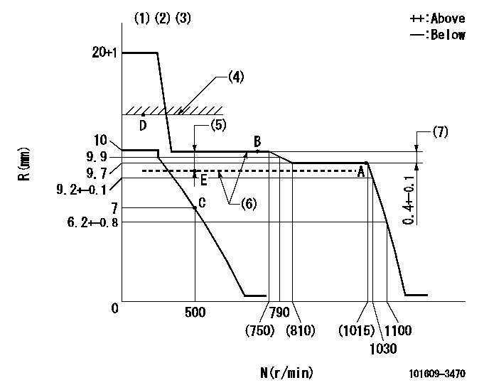
N:Pump speed
R:Rack position (mm)
(1)Target notch: K
(2)Tolerance for racks not indicated: +-0.05mm.
(3)Adjust the secondary timing before adjusting the governor.
(4)RACK LIMIT (When hydraulic cylinder is OFF)
(5)Boost compensator stroke: BCL
(6)When hydraulic cylinder ON: P1
(7)Rack difference between N = N1 and N = N2
----------
K=16 BCL=0.6+-0.1mm P1=((392)kPa,(4)kgf/cm2) N1=1000r/min N2=675r/min
----------
----------
K=16 BCL=0.6+-0.1mm P1=((392)kPa,(4)kgf/cm2) N1=1000r/min N2=675r/min
----------
Speed control lever angle
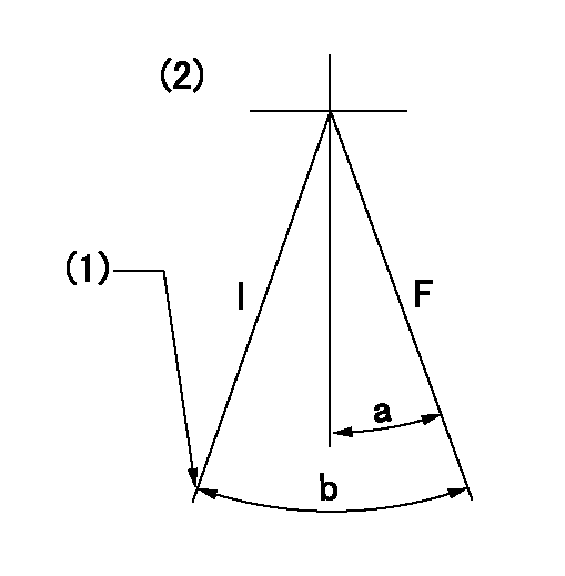
F:Full speed
I:Idle
(1)Stopper bolt setting
(2)Use the center hole at R = aa
----------
aa=77mm
----------
a=15deg+-3deg b=26deg+-5deg
----------
aa=77mm
----------
a=15deg+-3deg b=26deg+-5deg
Stop lever angle
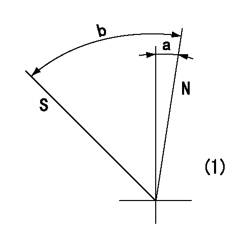
N:Pump normal
S:Stop the pump.
(1)No return spring
----------
----------
a=0deg+-5deg b=53deg+-5deg
----------
----------
a=0deg+-5deg b=53deg+-5deg
Timing setting
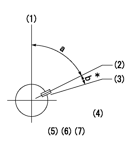
(1)Pump vertical direction
(2)Key groove position at No. 1 cylinder's beginning of injection position (at BTDC: aa).
(3)Position of the key groove of the No. 1 cylinder at B.T.D.C. bb (fix the governor flyweight at this position for delivery).
(4)B.T.D.C.: aa
(5)At second timing adjustment, set the camshaft at the * position and tighten the flyweight locknut.
(6)Align the flyweight's timing gear position with the lockpin groove and then fully tighten the flyweight to the camshaft.
(7)Remove the lock pin and adjust the governor. Reinstall the lock pin to fix the flyweight for delivery.
----------
aa=17deg bb=0deg
----------
a=54deg54min+-3deg b=8deg30min+-30min
----------
aa=17deg bb=0deg
----------
a=54deg54min+-3deg b=8deg30min+-30min
Information:
Caterpillar: Confidential Yellow
PSP FOR INSTALLING AN AUTOMATIC ETHER INJECTION SYSTEM (AEIS) ON CERTAIN D11N TRACTORS - PS4429 - MAILED US AND CANADA, COFA, CO SA, LIMITED CACO, LIMITED CFEL
The information supplied in this service letter may not be valid after the termination date of this program. Do not perform the work outlined in this Service Letter after the termination date without first contacting your Caterpillar product analyst.
U-33 A-25.1 AU-22 E-28.1 O-31 Revised 03/02/91 to correct part number error. In list of parts, 9X1047 Collar should read 9X0147 Collar. 1456 PS4429 This Program can be administered either before or after a failure. In either case the decision whether to apply the Program is made by the dealer. When reporting the repair, use "PS4429" as Part Number, "7755" as Group Number, and "96" as Description Code. Termination Date
February 29, 1992
Problem
Certain D11N Tractors equipped with a manual ether starting aid may experience problems during cold starts. An Automatic Ether Injection System (AEIS) can be installed to improve starting and combustion during cold startups and increase the service life of the engine.
Affected Product
Model Identification Number D11N 74Z1-729
Parts Needed
2 - 3B6768 Bushing 2 - 4B4274 Washer 2 - 8B0114 Spacer 8 - 8C5607 Mount 4 - 8C5608 Spacer 1 - 8C9006 Tee 1 - 8C9812 Switch Assembly 2 - 9D2867 Lens 2 - 9D3127 Base Assembly 2 - 8E0993 Plate 2 - 8E1355 Plate 1 - 8E1415 Valve Assembly 1 - 8E1446 Inlay 1 - 8E6595 Harness Assembly 1 - 9G9813 Alarm Group 1 - 4H1641 Pin 1 - 3J1907 Seal 1 - 3J5390 Plug 1 - 7J6596 Fitting Assembly 10 - 7K1181 Strap 1 - 2L8077 Terminal 1 - 2L8079 Terminal 8 - 4M0061 Bolt 8 - 5M3062 Bolt 1 - 8M2772 Clip 2 - 2N7456 Screw 2 - 7N5876
Have questions with 101609-3470?
Group cross 101609-3470 ZEXEL
Komatsu
Komatsu
101609-3470
9 400 615 907
3863834
INJECTION-PUMP ASSEMBLY
S6D102E
S6D102E
101609-3470
9 400 615 907
6735711440
INJECTION-PUMP ASSEMBLY
S6D102E
S6D102E

