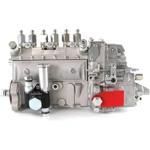
Information injection-pump assembly
ZEXEL
101609-3340
1016093340
Rating:
Service parts 101609-3340 INJECTION-PUMP ASSEMBLY:
1.
_
5.
AUTOM. ADVANCE MECHANIS
6.
COUPLING PLATE
7.
COUPLING PLATE
8.
_
9.
_
10.
NOZZLE AND HOLDER ASSY
11.
Nozzle and Holder
12.
Open Pre:MPa(Kqf/cm2)
21.6{220}
13.
NOZZLE-HOLDER
14.
NOZZLE
15.
NOZZLE SET
Include in #1:
101609-3340
as INJECTION-PUMP ASSEMBLY
Include in #2:
104058-3430
as _
Cross reference number
ZEXEL
101609-3340
1016093340
Zexel num
Bosch num
Firm num
Name
101609-3340
INJECTION-PUMP ASSEMBLY
Calibration Data:
Adjustment conditions
Test oil
1404 Test oil ISO4113 or {SAEJ967d}
1404 Test oil ISO4113 or {SAEJ967d}
Test oil temperature
degC
40
40
45
Nozzle and nozzle holder
105780-8140
Bosch type code
EF8511/9A
Nozzle
105780-0000
Bosch type code
DN12SD12T
Nozzle holder
105780-2080
Bosch type code
EF8511/9
Opening pressure
MPa
17.2
Opening pressure
kgf/cm2
175
Injection pipe
Outer diameter - inner diameter - length (mm) mm 6-2-600
Outer diameter - inner diameter - length (mm) mm 6-2-600
Overflow valve
131424-3420
Overflow valve opening pressure
kPa
255
221
289
Overflow valve opening pressure
kgf/cm2
2.6
2.25
2.95
Tester oil delivery pressure
kPa
157
157
157
Tester oil delivery pressure
kgf/cm2
1.6
1.6
1.6
Direction of rotation (viewed from drive side)
Right R
Right R
Injection timing adjustment
Direction of rotation (viewed from drive side)
Right R
Right R
Injection order
1-5-3-6-
2-4
Pre-stroke
mm
2.5
2.45
2.55
Beginning of injection position
Drive side NO.1
Drive side NO.1
Difference between angles 1
Cal 1-5 deg. 60 59.5 60.5
Cal 1-5 deg. 60 59.5 60.5
Difference between angles 2
Cal 1-3 deg. 120 119.5 120.5
Cal 1-3 deg. 120 119.5 120.5
Difference between angles 3
Cal 1-6 deg. 180 179.5 180.5
Cal 1-6 deg. 180 179.5 180.5
Difference between angles 4
Cyl.1-2 deg. 240 239.5 240.5
Cyl.1-2 deg. 240 239.5 240.5
Difference between angles 5
Cal 1-4 deg. 300 299.5 300.5
Cal 1-4 deg. 300 299.5 300.5
Injection quantity adjustment
Adjusting point
A
Rack position
8.9
Pump speed
r/min
1150
1150
1150
Average injection quantity
mm3/st.
81
80
82
Max. variation between cylinders
%
0
-2.5
2.5
Basic
*
Fixing the lever
*
Boost pressure
kPa
42.7
42.7
Boost pressure
mmHg
320
320
Hydraulic cylinder ON
*
Injection quantity adjustment_02
Adjusting point
C
Rack position
6.9+-0.5
Pump speed
r/min
400
400
400
Average injection quantity
mm3/st.
10
9
11
Max. variation between cylinders
%
0
-15
15
Fixing the rack
*
Boost pressure
kPa
0
0
0
Boost pressure
mmHg
0
0
0
Hydraulic cylinder ON
*
Injection quantity adjustment_03
Adjusting point
D
Rack position
-
Pump speed
r/min
100
100
100
Average injection quantity
mm3/st.
80
80
90
Fixing the lever
*
Boost pressure
kPa
0
0
0
Boost pressure
mmHg
0
0
0
Hydraulic cylinder OFF
*
Rack limit
*
Boost compensator adjustment
Pump speed
r/min
750
750
750
Rack position
R1-1.5
Boost pressure
kPa
7.3
4.6
10
Boost pressure
mmHg
55
35
75
Boost compensator adjustment_02
Pump speed
r/min
750
750
750
Rack position
R1(8.9)
Boost pressure
kPa
29.3
22.6
36
Boost pressure
mmHg
220
170
270
Test data Ex:
Governor adjustment
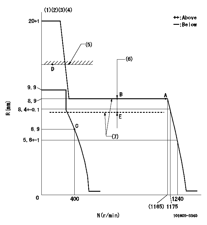
N:Pump speed
R:Rack position (mm)
(1)Target notch: K
(2)Tolerance for racks not indicated: +-0.05mm.
(3)The torque control spring does not operate.
(4)Adjust the secondary timing before adjusting the governor.
(5)RACK LIMIT (When hydraulic cylinder is OFF)
(6)Boost compensator stroke: BCL
(7)When hydraulic cylinder ON: P1
----------
K=10 BCL=1.5+-0.1mm P1=((392)kPa{(4)kgf/cm2})
----------
----------
K=10 BCL=1.5+-0.1mm P1=((392)kPa{(4)kgf/cm2})
----------
Speed control lever angle
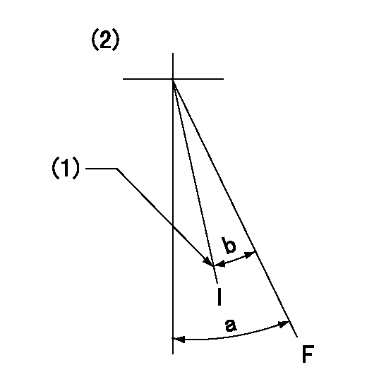
F:Full speed
I:Idle
(1)Stopper bolt setting
(2)At hole at R = aa (center)
----------
aa=80mm
----------
a=36deg+-3deg b=24deg+-5deg
----------
aa=80mm
----------
a=36deg+-3deg b=24deg+-5deg
Stop lever angle
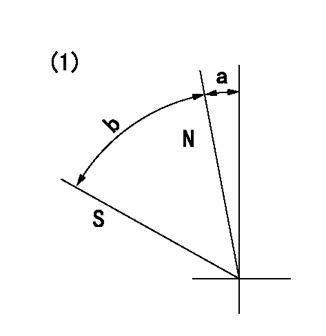
N:Pump normal
S:Stop the pump.
(1)Without return spring
----------
----------
a=0deg+-5deg b=53deg+-5deg
----------
----------
a=0deg+-5deg b=53deg+-5deg
Timing setting
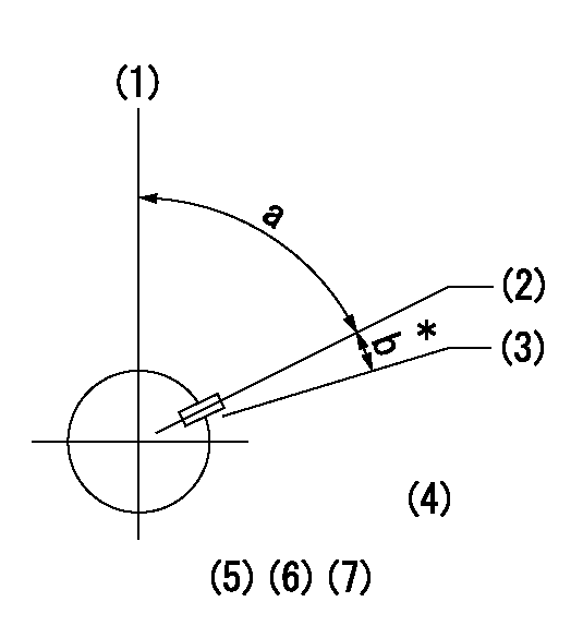
(1)Pump vertical direction
(2)Key groove position at No. 1 cylinder's beginning of injection position (at BTDC: aa).
(3)Position of the key groove of the No. 1 cylinder at B.T.D.C. bb (fix the governor flyweight at this position for delivery).
(4)B.T.D.C.: aa
(5)At second timing adjustment, set the camshaft at the * position and tighten the flyweight locknut.
(6)Align the flyweight's timing gear position with the lockpin groove and then fully tighten the flyweight to the camshaft.
(7)Remove the lock pin and adjust the governor. Reinstall the lock pin to fix the flyweight for delivery.
----------
aa=18deg bb=0deg
----------
a=54deg54min+-3deg b=9deg+-30min
----------
aa=18deg bb=0deg
----------
a=54deg54min+-3deg b=9deg+-30min
Information:
Start By:a. remove radiator 1. Attach lifting strap to engine compartment cover. Remove two cotter pins and washers (1), remove four bolts (2). Lift off cover. 2. Loosen hose clamps (3) and (4) and remove hose (5). Remove three bolts (6) and remove ether aid cover (7). 3. Disconnect ether aid line (8), electrical connector (9), and loosen eight 1/4 turn fasteners (10). Remove heat shields (11) and (12). 4. Mark and disconnect starter wires (13) and ground strap (14). 5. Mark and disconnect alternator wires (15) and (16), temperature sending unit wire (17), cable mounting bracket (18), and electrical connector (19). Disconnect and remove flexible exhaust pipe (20). Disconnect two heater hoses (21). 6. Disconnect throttle linkage (22), remove two bolts (23). Set throttle linkage mounting bracket aside. Shut off and disconnect two fuel lines (24). 7. Disconnect throttle cable clip (25). Disconnect electrical wire (26), electrical connector (27) and governor wiring (28). 8. Install tool (A), lifting strap and tool (B) as shown, to support hydraulic pump. Remove twelve hydraulic pump mounting bolts (29). 9. Install lifting chains and remove four bolts and bushings (30).10. Remove engine. The following steps are to install the engine.11. Position engine in vehicle and install four bolts and bushings (30).12. Connect hydraulic pump to engine with twelve mounting bolts (29).13. Remove tooling (A) and (B), and the lifting strap that was supporting the hydraulic pump.14. Connect governor wiring (28), electrical connector (27), and wire (26). Connect throttle cable clip (25).15. Connect two fuel lines (24). Position throttle linkage mounting bracket and secure with two bolts (23). Connect throttle linkage (22).16. Connect two heater hoses (21) and flexible exhaust pipe (20). Connect alternator wires (15) and (16), temperature sending unit wire (17), cable mounting bracket (18) and electrical connector (19).17. Connect starter wires (13) and ground strap (14).18. Replace heat shields (11) and (12), fasten with eight 1/4 turn fasteners. Connect electrical connector (9) and ether aid line (8).19. Replace ether aid cover (7) and secure with three bolts (6). Replace hose (5) and connect with clamps (3) and (4).20. Attach engine compartment cover with four bolts (2) and connect cylinders with cotter pins and washers (1).End By:a. install radiator
Have questions with 101609-3340?
Group cross 101609-3340 ZEXEL
Komatsu
Komatsu
Komatsu
101609-3340
INJECTION-PUMP ASSEMBLY
