Information injection-pump assembly
BOSCH
9 400 611 662
9400611662
ZEXEL
101609-3290
1016093290
Rating:
Service parts 101609-3290 INJECTION-PUMP ASSEMBLY:
1.
_


5.
AUTOM. ADVANCE MECHANIS
6.
COUPLING PLATE
7.
COUPLING PLATE
8.
_
9.
_
10.
NOZZLE AND HOLDER ASSY
11.
Nozzle and Holder
12.
Open Pre:MPa(Kqf/cm2)
21.6{220}
13.
NOZZLE-HOLDER
14.
NOZZLE
15.
NOZZLE SET
Include in #1:
101609-3290
as INJECTION-PUMP ASSEMBLY
Include in #2:
104257-1130
as _
Cross reference number
BOSCH
9 400 611 662
9400611662
ZEXEL
101609-3290
1016093290
Zexel num
Bosch num
Firm num
Name
Calibration Data:
Adjustment conditions
Test oil
1404 Test oil ISO4113 or {SAEJ967d}
1404 Test oil ISO4113 or {SAEJ967d}
Test oil temperature
degC
40
40
45
Nozzle and nozzle holder
105780-8140
Bosch type code
EF8511/9A
Nozzle
105780-0000
Bosch type code
DN12SD12T
Nozzle holder
105780-2080
Bosch type code
EF8511/9
Opening pressure
MPa
17.2
Opening pressure
kgf/cm2
175
Injection pipe
Outer diameter - inner diameter - length (mm) mm 6-2-600
Outer diameter - inner diameter - length (mm) mm 6-2-600
Overflow valve
131424-3420
Overflow valve opening pressure
kPa
255
221
289
Overflow valve opening pressure
kgf/cm2
2.6
2.25
2.95
Tester oil delivery pressure
kPa
157
157
157
Tester oil delivery pressure
kgf/cm2
1.6
1.6
1.6
Direction of rotation (viewed from drive side)
Right R
Right R
Injection timing adjustment
Direction of rotation (viewed from drive side)
Right R
Right R
Injection order
1-5-3-6-
2-4
Pre-stroke
mm
2.5
2.45
2.55
Beginning of injection position
Drive side NO.1
Drive side NO.1
Difference between angles 1
Cal 1-5 deg. 60 59.5 60.5
Cal 1-5 deg. 60 59.5 60.5
Difference between angles 2
Cal 1-3 deg. 120 119.5 120.5
Cal 1-3 deg. 120 119.5 120.5
Difference between angles 3
Cal 1-6 deg. 180 179.5 180.5
Cal 1-6 deg. 180 179.5 180.5
Difference between angles 4
Cyl.1-2 deg. 240 239.5 240.5
Cyl.1-2 deg. 240 239.5 240.5
Difference between angles 5
Cal 1-4 deg. 300 299.5 300.5
Cal 1-4 deg. 300 299.5 300.5
Injection quantity adjustment
Adjusting point
A
Rack position
9.4
Pump speed
r/min
1100
1100
1100
Average injection quantity
mm3/st.
93.5
92.5
94.5
Max. variation between cylinders
%
0
-2.5
2.5
Basic
*
Fixing the lever
*
Boost pressure
kPa
42.7
42.7
Boost pressure
mmHg
320
320
Hydraulic cylinder ON
*
Injection quantity adjustment_02
Adjusting point
C
Rack position
6.9+-0.5
Pump speed
r/min
400
400
400
Average injection quantity
mm3/st.
10
9
11
Max. variation between cylinders
%
0
-15
15
Fixing the rack
*
Boost pressure
kPa
0
0
0
Boost pressure
mmHg
0
0
0
Hydraulic cylinder ON
*
Injection quantity adjustment_03
Adjusting point
D
Rack position
-
Pump speed
r/min
100
100
100
Average injection quantity
mm3/st.
80
80
90
Fixing the lever
*
Boost pressure
kPa
0
0
0
Boost pressure
mmHg
0
0
0
Hydraulic cylinder OFF
*
Rack limit
*
Boost compensator adjustment
Pump speed
r/min
800
800
800
Rack position
7.9
Boost pressure
kPa
7.3
5
9.6
Boost pressure
mmHg
55
35
75
Boost compensator adjustment_02
Pump speed
r/min
800
800
800
Rack position
9.6
Boost pressure
kPa
29.3
22.6
36
Boost pressure
mmHg
220
170
270
Test data Ex:
Governor adjustment
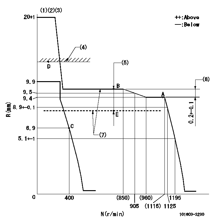
N:Pump speed
R:Rack position (mm)
(1)Target notch: K
(2)Tolerance for racks not indicated: +-0.05mm.
(3)Adjust the secondary timing before adjusting the governor.
(4)RACK LIMIT (When hydraulic cylinder is OFF)
(5)Boost compensator stroke: BCL
(6)Rack difference between N = N1 and N = N2
(7)When hydraulic cylinder ON: P1
----------
K=12 BCL=1.7+-0.1mm N1=1100r/min N2=800r/min P1=((392)kPa{(4)kgf/cm2})
----------
----------
K=12 BCL=1.7+-0.1mm N1=1100r/min N2=800r/min P1=((392)kPa{(4)kgf/cm2})
----------
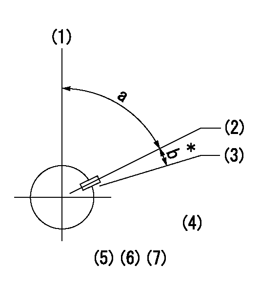
Speed control lever angle
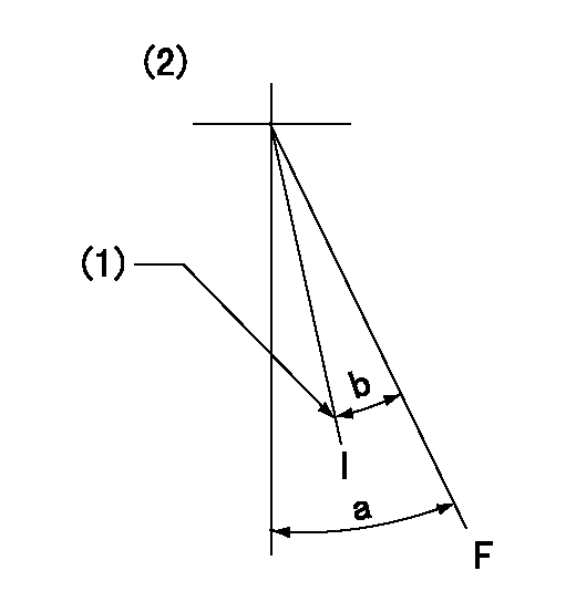
F:Full speed
I:Idle
(1)Stopper bolt setting
(2)At hole at R = aa (center)
----------
aa=80mm
----------
a=37deg+-3deg b=34deg+-5deg
----------
aa=80mm
----------
a=37deg+-3deg b=34deg+-5deg
Stop lever angle
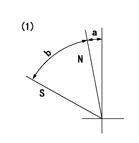
N:Pump normal
S:Stop the pump.
(1)Without return spring
----------
----------
a=0deg+-5deg b=53deg+-5deg
----------
----------
a=0deg+-5deg b=53deg+-5deg
Timing setting
(1)Pump vertical direction
(2)Key groove position at No. 1 cylinder's beginning of injection position (at BTDC: aa).
(3)Position of the key groove of the No. 1 cylinder at B.T.D.C. bb (fix the governor flyweight at this position for delivery).
(4)B.T.D.C.: aa
(5)At second timing adjustment, set the camshaft at the * position and tighten the flyweight locknut.
(6)Align the flyweight's timing gear position with the lockpin groove and then fully tighten the flyweight to the camshaft.
(7)Remove the lock pin and adjust the governor. Reinstall the lock pin to fix the flyweight for delivery.
----------
aa=18deg bb=0deg
----------
a=54deg54min+-3deg b=9deg+-30min
----------
aa=18deg bb=0deg
----------
a=54deg54min+-3deg b=9deg+-30min
Information:
(1) Inside diameter of rocker arm ... 19.063 to 19.101 mm (.7505 to 7520 in) Lever clearance on rocker shaft ... 0.03 to 0.089 mm (.001 to .0035 in)Maximum permissible clearance (worn) ... 0.13 mm (.005 in)(2) Diameter of rocker shaft ... 19.012 to 19.037 mm (.7485 to .7495 in)(3) Install seal (3) in cylinder head before rocker shaft is installed.(4) Length of push rods ... 270.46 to 271.98 mm (10.648 to 10.708 in) Diameter of push rods ... 7.87 to 7.92 mm (.310 to .312 in)(5) End play of camshaft (new) ... 0.10 to 0.41 mm (.004 to .016 in) Maximum permissible end play (worn) ... 0.51 mm (.020 in)(6) Torque for bolt that holds camshaft gear on camshaft ... 70 N m (50 lb ft)(7) Camshaft thrust washer. A new cylinder block, camshaft and thrust washer have been introduced on the 4.236 engine for the Backhoe Loaders. The thrust washer recess in the new block is deeper. The thrust washer thickness remains the same. The change became effective with engine serial number LD70178U106654N. The engine serial number is located above the fuel injection pump on the block.Outside diameter of thrust washer ... 72.95 to 73.00 mm (2.872 to 2.874 in)Cylinder block recess diameter for thrust washer ... 73.03 to 73.28 mm (2.875 to 2.885 in)Clearance of thrust washer in recess ... 0.03 to 0.33 mm (.001 to .013 in)Inside diameter of thrust washer ... 44.45 mm (1.750 in)Thickness of thrust washer ... 5.49 to 5.54 mm (.216 to .218 in) The recess in the cylinder block is deeper for current models.Earlier Models:Cylinder block recess depth for thrust washer ... 4.75 to 4.83 mm (.187 to .190 in)Projection of thrust washer above cylinder block front face ... 0.66 to 0.79 mm (.026 to .031 in)Current Models:Cylinder block recess depth for thrust washer ... 5.38 to 5.49 mm (.212 to .216 in)Projection of thrust washer above cylinder block front face ... 0.0 to 0.13 mm (0.0 to .005 in)(8) Diameter of camshaft journals: No. 1 journal ... 50.71 to 50.737 mm (1.9965 to 1.9975 in)Minimum permissible diameter ... 50.660 mm (1.9945 in)No. 2 journal ... 50.457 to 50.483 mm (1.9865 to 1.9875 in)Minimum permissible diameter ... 50.406 mm (1.9845 in)No. 3 journal ... 49.949 to 49.975 mm (1.9665 to 1.9675 in)Minimum permissible diameter ... 49.898 mm (19.9645 in)See Cylinder Block for camshaft bore specifications.(9) Tappet (valve lifter): Length of tappet ... 75.4063 mm (2.96875 in)Shank diameter ... 18.987 to 19.012 mm (.7475 to .7485 in)Diameter of bore in block for tappet ... 19.05 to 19.083 mm (.750 to .7513 in)Running clearance between tappet and block ... 0.038 to 0.097 mm (.0015 to .0038 in)Foot diameter of tappet ... 30.163 mm (1.1875 in) Camshaft lobe height: 1. Measure base circle (C).2. Add lobe lift (A) to base circle measurement. Camshaft lobe lift (A) is ... 7.62 to 7.70 mm (.300 to .303 in)3. Total is camshaft lobe height (B). Minimum