Information injection-pump assembly
BOSCH
F 019 Z10 970
f019z10970
ZEXEL
101495-3550
1014953550
KOMATSU
6205711540
6205711540
Rating:
Service parts 101495-3550 INJECTION-PUMP ASSEMBLY:
1.
_

5.
AUTOM. ADVANCE MECHANIS
6.
COUPLING PLATE
7.
COUPLING PLATE
8.
_
9.
_

11.
Nozzle and Holder
12.
Open Pre:MPa(Kqf/cm2)
19.6{200}

15.
NOZZLE SET
Include in #1:
101495-3550
as INJECTION-PUMP ASSEMBLY
Include in #2:
104741-7380
as _
Cross reference number
BOSCH
F 019 Z10 970
f019z10970
ZEXEL
101495-3550
1014953550
KOMATSU
6205711540
6205711540
Zexel num
Bosch num
Firm num
Name
F 019 Z10 970
6205711540 KOMATSU
INJECTION-PUMP ASSEMBLY
S4D95LE-3 * K 14BC INJECTION PUMP ASSY PE4A,5A, PE
S4D95LE-3 * K 14BC INJECTION PUMP ASSY PE4A,5A, PE
Calibration Data:
Adjustment conditions
Test oil
1404 Test oil ISO4113 or {SAEJ967d}
1404 Test oil ISO4113 or {SAEJ967d}
Test oil temperature
degC
40
40
45
Nozzle and nozzle holder
105780-8140
Bosch type code
EF8511/9A
Nozzle
105780-0000
Bosch type code
DN12SD12T
Nozzle holder
105780-2080
Bosch type code
EF8511/9
Opening pressure
MPa
17.2
Opening pressure
kgf/cm2
175
Injection pipe
Outer diameter - inner diameter - length (mm) mm 6-2-600
Outer diameter - inner diameter - length (mm) mm 6-2-600
Tester oil delivery pressure
kPa
157
157
157
Tester oil delivery pressure
kgf/cm2
1.6
1.6
1.6
Direction of rotation (viewed from drive side)
Right R
Right R
Injection timing adjustment
Direction of rotation (viewed from drive side)
Right R
Right R
Injection order
1-2-4-3
Pre-stroke
mm
3.2
3.15
3.25
Rack position
After adjusting injection quantity. R=A
After adjusting injection quantity. R=A
Beginning of injection position
Drive side NO.1
Drive side NO.1
Difference between angles 1
Cyl.1-2 deg. 90 89.5 90.5
Cyl.1-2 deg. 90 89.5 90.5
Difference between angles 2
Cal 1-4 deg. 180 179.5 180.5
Cal 1-4 deg. 180 179.5 180.5
Difference between angles 3
Cal 1-3 deg. 270 269.5 270.5
Cal 1-3 deg. 270 269.5 270.5
Injection quantity adjustment
Adjusting point
A
Rack position
9.2
Pump speed
r/min
925
925
925
Average injection quantity
mm3/st.
63.5
62.5
64.5
Max. variation between cylinders
%
0
-2.5
2.5
Basic
*
Fixing the lever
*
Boost pressure
kPa
54.7
54.7
Boost pressure
mmHg
410
410
Injection quantity adjustment_02
Adjusting point
-
Rack position
7.8+-0.5
Pump speed
r/min
415
415
415
Average injection quantity
mm3/st.
13.5
12.5
14.5
Max. variation between cylinders
%
0
-15
15
Fixing the rack
*
Boost pressure
kPa
0
0
0
Boost pressure
mmHg
0
0
0
Remarks
Adjust only variation between cylinders; adjust governor according to governor specifications.
Adjust only variation between cylinders; adjust governor according to governor specifications.
Injection quantity adjustment_03
Adjusting point
E
Rack position
-
Pump speed
r/min
100
100
100
Average injection quantity
mm3/st.
62
52
72
Fixing the lever
*
Boost pressure
kPa
0
0
0
Boost pressure
mmHg
0
0
0
Remarks
Rack cap
Rack cap
Boost compensator adjustment
Pump speed
r/min
400
400
400
Rack position
8.5
Boost pressure
kPa
8.7
6
11.4
Boost pressure
mmHg
65
45
85
Boost compensator adjustment_02
Pump speed
r/min
400
400
400
Rack position
8.8
Boost pressure
kPa
18
15.3
20.7
Boost pressure
mmHg
135
115
155
Boost compensator adjustment_03
Pump speed
r/min
400
400
400
Rack position
(9.5)
Boost pressure
kPa
41.3
41.3
41.3
Boost pressure
mmHg
310
310
310
Test data Ex:
Governor adjustment
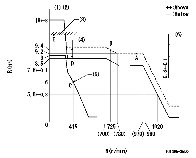
N:Pump speed
R:Rack position (mm)
(1)Target notch: K
(2)Tolerance for racks not indicated: +-0.05mm.
(3)RACK CAP: R1
(4)Boost compensator stroke: BCL
(5)Set the idle spring.
(6)Rack difference between N = N1 and N = N2
----------
K=10 R1=(17.5)mm BCL=(1)mm N1=925r/min N2=600r/min
----------
----------
K=10 R1=(17.5)mm BCL=(1)mm N1=925r/min N2=600r/min
----------
Speed control lever angle
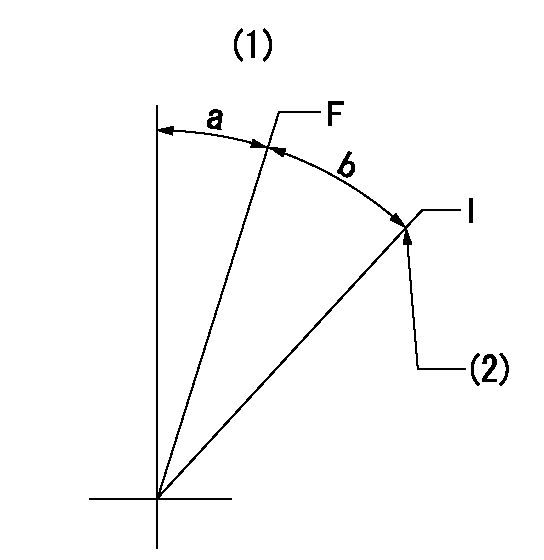
F:Full speed
I:Idle
(1)Use the hole at R = aa
(2)Stopper bolt setting
----------
aa=60mm
----------
a=6deg+-5deg b=17deg+-5deg
----------
aa=60mm
----------
a=6deg+-5deg b=17deg+-5deg
Stop lever angle
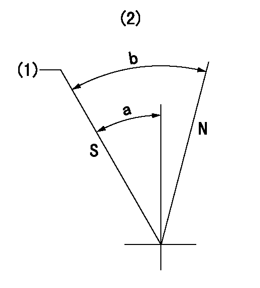
N:Pump normal
S:Stop the pump.
(1)Rack position = aa, speed = bb (stamp at delivery)
(2)No return spring
----------
aa=1-0.5mm bb=0r/min
----------
a=27.5deg+-5deg b=(55deg)
----------
aa=1-0.5mm bb=0r/min
----------
a=27.5deg+-5deg b=(55deg)
0000001501 TAMPER PROOF

Tamperproofing-equipped boost compensator cover installation procedure
(A) After adjusting the boost compensator, tighten the bolts to remove the heads.
(1)Before adjusting the governor and the boost compensator, tighten the screw to the specified torque.
(Tightening torque T = T1 maximum)
(2)After adjusting the governor and the boost compensator, tighten to the specified torque to break off the bolt heads.
(Tightening torque T = T2)
----------
T1=2.5N-m(0.25kgf-m) T2=2.9~4.4N-m(0.3~0.45kgf-m)
----------
----------
T1=2.5N-m(0.25kgf-m) T2=2.9~4.4N-m(0.3~0.45kgf-m)
----------
0000001601 I/P WITH LOAD PLUNGER ADJ
Load plunger-equipped pump adjustment
1. Adjust the variation between cylinders and the injection quantity.
2. At Full point A, adjust the pre-stroke to the specified value.
3. After pre-stroke adjustment, reconfirm that the fuel injection quantity and the variation between cylinders is as specified.
----------
----------
----------
----------
Timing setting

(1)Pump vertical direction
(2)Position of key groove at No 1 cylinder's beginning of injection
(3)Stamp aligning marks on the pump housing flange.
(4)B.T.D.C.: aa
(5)After adjusting the injection quantity, adjust at rack position bb.
----------
aa=5deg bb=9.2mm
----------
a=58deg+-3deg b=2deg+-30min
----------
aa=5deg bb=9.2mm
----------
a=58deg+-3deg b=2deg+-30min
Information:
A pressurized cooling system serves two purposes. First, it permits safe operation at coolant temperatures higher than the normal boiling point; thereby, providing a margin of cooling for those intermittent peak loads. Secondly, it prevents cavitation in the water pump and reduces the possibility of air or steam pockets forming in the coolant passages.Many times engine overheating is caused by failure to make simple systematic inspections. Visual inspections should be made before testing. Coolant Level: Check the engine coolant level with engine stopped and cool. Always release cooling system pressure before checking. Fill to the proper level with water, as free as possible from scale forming minerals, not softened water. During freezing weather add sufficient permanent type antifreeze to the coolant to prevent freezing. Make up water added without the proper proportions of inhibitor can cause excessive mineral deposits. (Use inhibitor as recommended on container.)Most commercial antifreeze solutions contain rust inhibitors, however, it is recommended the adding of Caterpillar Coolant System Inhibitor to glycol base antifreeze if protection is for temperatures above -20°F (-29°C). If protection is for temperatures -20°F (-29°C) or below, do not add inhibitor.
Inhibitor contains alkali. Avoid contact with eyes. Avoid prolonged or repeated contact with skin.
Add coolant slowly to a hot engine (engine running) to prevent possible cracking or distorting the cylinder heads.
If a loss of coolant is noticeable, check for leaks in the system. After filling the system, start the engine and add coolant as necessary to maintain a full system during engine warm up. Running the engine at operating temperature will permit the temperature regulator to open and allow the coolant to circulate and purge air from the entire system. Some systems will normally loose some coolant during initial warm up cycle. Cleaning the Radiator (External): Clean dirt and trash from between the tubes of the radiator. Accumulation of debris may cause excessively high operating temperature. Wash, brush or blow the dirt out with whichever method is available and most effective. When cleaning with air do not exceed 30 PSI (2 kg/cm2). Cleaning the Cooling System (Internal): Clean the cooling system periodically. Mineral deposits can cause serious engine damage by retarding the transfer of heat to the coolant. A deposit of lime 1/32 inch thick insulates the same amount as 2 inches of steel, reducing the heat transfer substantially. Loose scale and sediment deposited in the cooling system will reduce circulation, resulting in possible engine damage. To clean, stop the engine when it is at normal operating temperature and drain as quickly as possible. Flush thoroughly, then fill with a solution of 3.2 ounces of Oxalic Acid or Sodium Bisulfate per one gallon of water. Run the engine at operating temperature one-half to one hour, then drain and flush until water is clear. Fill with a solution of .8 of an ounce of Sal Soda per one gallon of water and run the engine ten minutes. Drain, flush and fill with water, adding corrosion inhibitor or the desired amount of antifreeze.
ENGINE DRAIN