Information injection-pump assembly
BOSCH
9 400 619 824
9400619824
ZEXEL
101495-3531
1014953531
KOMATSU
6208711210
6208711210
Rating:
You can express buy:
Service parts 101495-3531 INJECTION-PUMP ASSEMBLY:
1.
_
5.
AUTOM. ADVANCE MECHANIS
6.
COUPLING PLATE
7.
COUPLING PLATE
8.
_
9.
_
11.
Nozzle and Holder
12.
Open Pre:MPa(Kqf/cm2)
19.6(200)
15.
NOZZLE SET
Include in #1:
101495-3531
as INJECTION-PUMP ASSEMBLY
Include in #2:
104741-7330
as _
Cross reference number
BOSCH
9 400 619 824
9400619824
ZEXEL
101495-3531
1014953531
KOMATSU
6208711210
6208711210
Zexel num
Bosch num
Firm num
Name
101495-3531
9 400 619 824
6208711210 KOMATSU
INJECTION-PUMP ASSEMBLY
SAA4D95LE K 14BC INJECTION PUMP ASSY PE4A,5A, PE
SAA4D95LE K 14BC INJECTION PUMP ASSY PE4A,5A, PE
Calibration Data:
Adjustment conditions
Test oil
1404 Test oil ISO4113 or {SAEJ967d}
1404 Test oil ISO4113 or {SAEJ967d}
Test oil temperature
degC
40
40
45
Nozzle and nozzle holder
105780-8140
Bosch type code
EF8511/9A
Nozzle
105780-0000
Bosch type code
DN12SD12T
Nozzle holder
105780-2080
Bosch type code
EF8511/9
Opening pressure
MPa
17.2
Opening pressure
kgf/cm2
175
Injection pipe
Outer diameter - inner diameter - length (mm) mm 6-2-600
Outer diameter - inner diameter - length (mm) mm 6-2-600
Overflow valve
131425-1420
Overflow valve opening pressure
kPa
255
221
289
Overflow valve opening pressure
kgf/cm2
2.6
2.25
2.95
Tester oil delivery pressure
kPa
255
255
255
Tester oil delivery pressure
kgf/cm2
2.6
2.6
2.6
Direction of rotation (viewed from drive side)
Right R
Right R
Injection timing adjustment
Direction of rotation (viewed from drive side)
Right R
Right R
Injection order
1-2-4-3
Pre-stroke
mm
3.2
3.15
3.25
Rack position
After adjusting injection quantity. R=A
After adjusting injection quantity. R=A
Beginning of injection position
Drive side NO.1
Drive side NO.1
Difference between angles 1
Cyl.1-2 deg. 90 89.5 90.5
Cyl.1-2 deg. 90 89.5 90.5
Difference between angles 2
Cal 1-4 deg. 180 179.5 180.5
Cal 1-4 deg. 180 179.5 180.5
Difference between angles 3
Cal 1-3 deg. 270 269.5 270.5
Cal 1-3 deg. 270 269.5 270.5
Injection quantity adjustment
Adjusting point
A
Rack position
10.1
Pump speed
r/min
1100
1100
1100
Average injection quantity
mm3/st.
80.5
79.5
81.5
Max. variation between cylinders
%
0
-2.5
2.5
Basic
*
Fixing the lever
*
Boost pressure
kPa
45.3
45.3
Boost pressure
mmHg
340
340
Injection quantity adjustment_02
Adjusting point
-
Rack position
7.3+-0.5
Pump speed
r/min
550
550
550
Average injection quantity
mm3/st.
13
12
14
Max. variation between cylinders
%
0
-15
15
Fixing the rack
*
Boost pressure
kPa
0
0
0
Boost pressure
mmHg
0
0
0
Remarks
Adjust only variation between cylinders; adjust governor according to governor specifications.
Adjust only variation between cylinders; adjust governor according to governor specifications.
Injection quantity adjustment_03
Adjusting point
E
Rack position
10.6++
Pump speed
r/min
100
100
100
Average injection quantity
mm3/st.
61
56
66
Fixing the lever
*
Boost pressure
kPa
0
0
0
Boost pressure
mmHg
0
0
0
Rack limit
*
Boost compensator adjustment
Pump speed
r/min
750
750
750
Rack position
R2-1.55
Boost pressure
kPa
6.7
5.4
8
Boost pressure
mmHg
50
40
60
Boost compensator adjustment_02
Pump speed
r/min
750
750
750
Rack position
R2-1.15
Boost pressure
kPa
13.3
12
14.6
Boost pressure
mmHg
100
90
110
Boost compensator adjustment_03
Pump speed
r/min
750
750
750
Rack position
R2(10.4)
Boost pressure
kPa
32
32
32
Boost pressure
mmHg
240
240
240
Test data Ex:
Governor adjustment
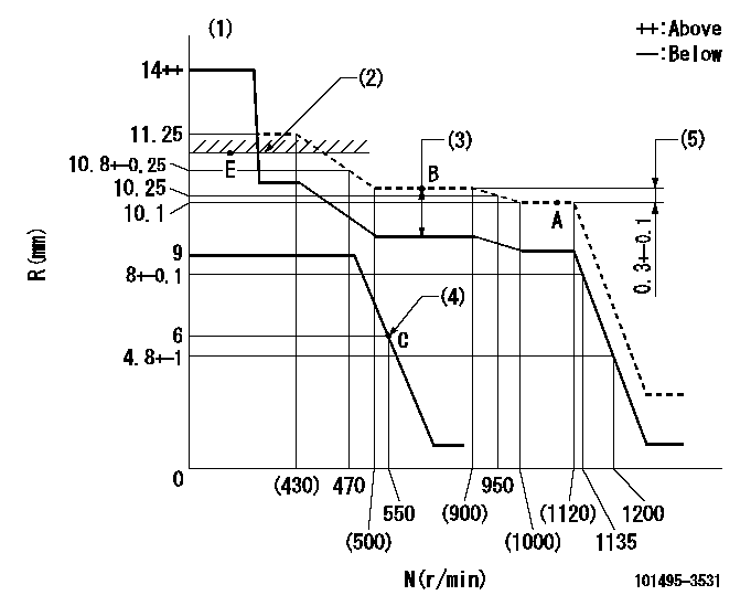
N:Pump speed
R:Rack position (mm)
(1)Target notch: K
(2)RACK LIMIT
(3)Boost compensator stroke: BCL
(4)Set idle sub-spring
(5)Rack difference between N = N1 and N = N2
----------
K=10 BCL=1.55+-0.1mm N1=1100r/min N2=750r/min
----------
----------
K=10 BCL=1.55+-0.1mm N1=1100r/min N2=750r/min
----------
Speed control lever angle
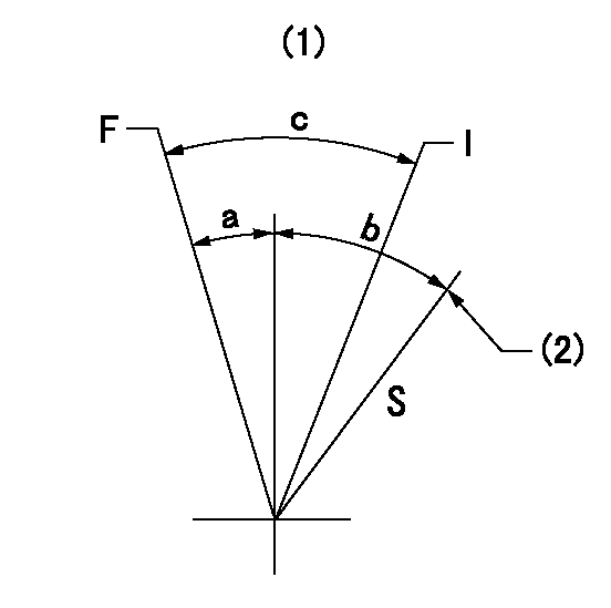
F:Full speed
I:Idle
S:Stop
(1)Use hole at R = aa (middle hole)
(2)Stopper bolt setting
----------
aa=80mm
----------
a=3deg+-3deg b=35deg+-3deg c=27deg+-5deg
----------
aa=80mm
----------
a=3deg+-3deg b=35deg+-3deg c=27deg+-5deg
0000001501 TAMPER PROOF
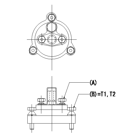
Tamperproofing-equipped boost compensator cover installation procedure
(A): After adjusting the boost compensator, assemble then tighten the bolts to remove the heads.
(B): Specified torque
(1)Before adjusting the governor and the boost compensator, tighten the screw to the specified torque.
(Tightening torque T = T1 maximum)
(2)After adjusting the governor and the boost compensator, tighten to the specified torque to break off the bolt heads.
(Tightening torque T = T2)
----------
T1=2.5N-m(0.25kgf-m) T2=2.9~4.4N-m(0.3~0.45kgf-m)
----------
----------
T1=2.5N-m(0.25kgf-m) T2=2.9~4.4N-m(0.3~0.45kgf-m)
----------
0000001601 I/P WITH LOAD PLUNGER ADJ
Load plunger-equipped pump adjustment
1. Adjust the variation between cylinders and the injection quantity.
2. At Full point A, adjust the pre-stroke to the specified value.
3. After pre-stroke adjustment, reconfirm that the fuel injection quantity and the variation between cylinders is as specified.
----------
----------
----------
----------
Timing setting
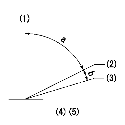
(1)Pump vertical direction
(2)Position of key groove at No 1 cylinder's beginning of injection
(3)Stamp aligning marks on the pump housing flange.
(4)B.T.D.C.: aa
(5)After adjusting the injection quantity, adjust at rack position bb.
----------
aa=7.4deg bb=10.1mm
----------
a=58deg+-3deg b=2deg+-30min
----------
aa=7.4deg bb=10.1mm
----------
a=58deg+-3deg b=2deg+-30min
Information:
CHECK CRANKCASE OIL LEVEL before starting and when refueling. The dipstick has 2 marks, and the distance between them represents 3 quarts. Always check oil with engine stopped and truck on level ground. Use oils meeting the following engine service classification:SC and SD (MS - Motor Severe Oils)CB (Supplement 1 Oils)CC (MIL-L-2104B or MIL-L-46152 Specification Oils)CD or MIL-L-2104CChange engine oil and filters as specified in the Lubrication and Maintenance Charts. CHECK ENGINE COOLANT LEVEL (with engine stopped). Always release cooling system pressure before checking. Fill to the proper level with water, free as possible from scale-forming minerals (not softened water), and rust inhibitor, or a solution of water and a permanent type anti-freeze containing rust inhibitor. It is recommended Caterpillar Coolant System Inhibitor be added to the coolant solution if protection is for temperatures above -20°F (-29°C). It is not necessary to add inhibitor to the coolant solution if protection is for temperatures -20°F (-29°C) and below.Models equipped with sight gauge; coolant should be warm (engine stopped) and coolant should be visible in the sight gauge.
Inhibitor contains alkali. Avoid contact with skin and eyes.
CHECK RADIATOR for dirt and foreign material, fan, water pump and accessory drive belts for cracks, breaks and frayed edges. While checking belts, also check for oil, water and fuel leaks and general appearance of engine and engine compartment. CHECK FUEL SUPPLY: Drain a cupful of fuel from the bottom of the tank to remove water or sediment.Fill fuel tanks after completing a run. Partially filled tanks will collect moisture if the truck is parked for any length of time. Use No. 2D diesel fuel in Caterpillar 1100 Series Diesel Truck Engines. Use No. 1-D diesel fuel in cold temperatures when white smoke must be minimized on start up. Keep fuel clean. Refer to Fuel Specifications for detailed information on fuel selection.
Have questions with 101495-3531?
Group cross 101495-3531 ZEXEL
Komatsu
Komatsu
101495-3531
9 400 619 824
6208711210
INJECTION-PUMP ASSEMBLY
SAA4D95LE
SAA4D95LE

