Information injection-pump assembly
BOSCH
9 400 613 168
9400613168
ZEXEL
101495-3490
1014953490
KOMATSU
6205711350
6205711350
Rating:
Compare Prices: .
As an associate, we earn commssions on qualifying purchases through the links below
Aftermarket Fuel Injection Pump 6205-71-1350 101049-4100 Fit Intended For Engine S4D95LE-3 Excavator PC78MR-6 PC78US-6
Generic
Generic
Excavator Fuel Pump Replacement Part 1014953490
ACHMRJIJ Designed Compatible with reliability, the Oil Fuel Pump 101495-3490 fits a wide range of excavator models, ensuring compatibility across various machinery. || Engineered to enhance performance, this fuel pump optimizes fuel delivery to your excavator, resulting in improved efficiency and smoother. || Constructed with materials, the Oil Fuel Pump 101495-3490 is built to withstand harsh working conditions, ensuring durability and longevity in demanding environments. || Simple installation process allows Compatible with quick replacement, downtime and keeping your excavator operational when you need it most. || engineering ensures consistent fuel flow, enhancing the overall functionality of your excavator and contributing to effective on the job site. || Designed Compatible with fuel efficiency, this pump helps reduce overall fuel consumption, saving you money while maximizing performance. || Backed by industry standards, the Oil Fuel Pump 101495-3490 meets rigorous testing criteria, providing peace of mind that you are using a reliable component Compatible with your excavator.
ACHMRJIJ Designed Compatible with reliability, the Oil Fuel Pump 101495-3490 fits a wide range of excavator models, ensuring compatibility across various machinery. || Engineered to enhance performance, this fuel pump optimizes fuel delivery to your excavator, resulting in improved efficiency and smoother. || Constructed with materials, the Oil Fuel Pump 101495-3490 is built to withstand harsh working conditions, ensuring durability and longevity in demanding environments. || Simple installation process allows Compatible with quick replacement, downtime and keeping your excavator operational when you need it most. || engineering ensures consistent fuel flow, enhancing the overall functionality of your excavator and contributing to effective on the job site. || Designed Compatible with fuel efficiency, this pump helps reduce overall fuel consumption, saving you money while maximizing performance. || Backed by industry standards, the Oil Fuel Pump 101495-3490 meets rigorous testing criteria, providing peace of mind that you are using a reliable component Compatible with your excavator.
Service parts 101495-3490 INJECTION-PUMP ASSEMBLY:
1.
_
5.
AUTOM. ADVANCE MECHANIS
6.
COUPLING PLATE
7.
COUPLING PLATE
8.
_
9.
_
11.
Nozzle and Holder
12.
Open Pre:MPa(Kqf/cm2)
19.6{200}
15.
NOZZLE SET
Cross reference number
BOSCH
9 400 613 168
9400613168
ZEXEL
101495-3490
1014953490
KOMATSU
6205711350
6205711350
Zexel num
Bosch num
Firm num
Name
9 400 613 168
6205711350 KOMATSU
INJECTION-PUMP ASSEMBLY
S4D95LE-3 * K 14BC INJECTION PUMP ASSY PE4A,5A, PE
S4D95LE-3 * K 14BC INJECTION PUMP ASSY PE4A,5A, PE
Calibration Data:
Adjustment conditions
Test oil
1404 Test oil ISO4113 or {SAEJ967d}
1404 Test oil ISO4113 or {SAEJ967d}
Test oil temperature
degC
40
40
45
Nozzle and nozzle holder
105780-8140
Bosch type code
EF8511/9A
Nozzle
105780-0000
Bosch type code
DN12SD12T
Nozzle holder
105780-2080
Bosch type code
EF8511/9
Opening pressure
MPa
17.2
Opening pressure
kgf/cm2
175
Injection pipe
Outer diameter - inner diameter - length (mm) mm 6-2-600
Outer diameter - inner diameter - length (mm) mm 6-2-600
Tester oil delivery pressure
kPa
157
157
157
Tester oil delivery pressure
kgf/cm2
1.6
1.6
1.6
Direction of rotation (viewed from drive side)
Right R
Right R
Injection timing adjustment
Direction of rotation (viewed from drive side)
Right R
Right R
Injection order
1-2-4-3
Pre-stroke
mm
3.2
3.15
3.25
Rack position
After adjusting injection quantity. R=A
After adjusting injection quantity. R=A
Beginning of injection position
Drive side NO.1
Drive side NO.1
Difference between angles 1
Cyl.1-2 deg. 90 89.5 90.5
Cyl.1-2 deg. 90 89.5 90.5
Difference between angles 2
Cal 1-4 deg. 180 179.5 180.5
Cal 1-4 deg. 180 179.5 180.5
Difference between angles 3
Cal 1-3 deg. 270 269.5 270.5
Cal 1-3 deg. 270 269.5 270.5
Injection quantity adjustment
Adjusting point
A
Rack position
10.8
Pump speed
r/min
925
925
925
Average injection quantity
mm3/st.
63
62
64
Max. variation between cylinders
%
0
-2.5
2.5
Basic
*
Fixing the lever
*
Injection quantity adjustment_02
Adjusting point
-
Rack position
8.3+-0.5
Pump speed
r/min
575
575
575
Average injection quantity
mm3/st.
8
7
9
Max. variation between cylinders
%
0
-15
15
Fixing the rack
*
Remarks
Adjust only variation between cylinders; adjust governor according to governor specifications.
Adjust only variation between cylinders; adjust governor according to governor specifications.
Test data Ex:
Governor adjustment
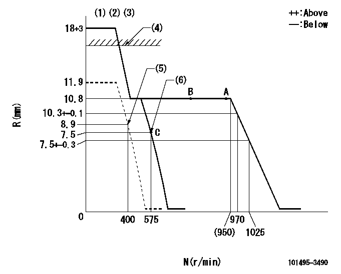
N:Pump speed
R:Rack position (mm)
(1)Target notch: K
(2)Tolerance for racks not indicated: +-0.05mm.
(3)Deliver without the torque control spring operating.
(4)RACK CAP: R1
(5)Set idle sub-spring
(6)Main spring setting
----------
K=6 R1=(17.5)mm
----------
----------
K=6 R1=(17.5)mm
----------
Speed control lever angle
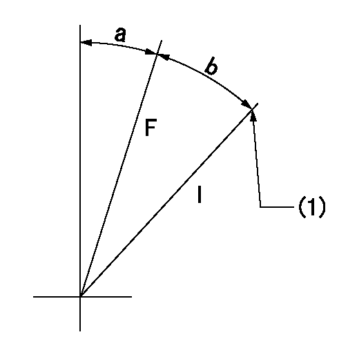
F:Full speed
I:Idle
(1)Stopper bolt setting
----------
----------
a=7deg+-5deg b=13deg+-5deg
----------
----------
a=7deg+-5deg b=13deg+-5deg
Stop lever angle
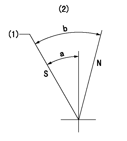
N:Pump normal
S:Stop the pump.
(1)Rack position = aa, speed = bb (stamp at delivery)
(2)No return spring
----------
aa=1-0.5mm bb=0r/min
----------
a=27.5deg+-5deg b=(55deg)
----------
aa=1-0.5mm bb=0r/min
----------
a=27.5deg+-5deg b=(55deg)
0000001501 I/P WITH LOAD PLUNGER ADJ
Load plunger-equipped pump adjustment
1. Adjust the variation between cylinders and the injection quantity.
2. At Full point A, adjust the pre-stroke to the specified value.
3. After pre-stroke adjustment, reconfirm that the fuel injection quantity and the variation between cylinders is as specified.
----------
----------
----------
----------
Timing setting
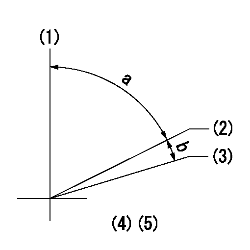
(1)Pump vertical direction
(2)Position of key groove at No 1 cylinder's beginning of injection
(3)Stamp aligning marks on the pump housing flange.
(4)After adjusting the injection quantity, adjust at rack position aa.
----------
aa=10.8mm
----------
a=58deg+-3deg b=2deg+-30min
----------
aa=10.8mm
----------
a=58deg+-3deg b=2deg+-30min
Information:
The fuel system is a pressure type with a separate injection pump and injection valve for each cylinder. Fuel is injected into a precombustion chamber, not directly into the cylinder.A transfer pump supplies fuel filtered through primary (optional) and final filters to a manifold in the injection pump housing.The transfer pump supplies more fuel than is required for injection, so a bypass valve is built into the pressure side of the pump. The valve limits the maximum pressure within the supply system.An air vent valve located on the fuel filter base permits the removal of air in the injection pump supply system after servicing the filter or whenever air is allowed to enter the system. Air is removed by opening the valve and pressurizing the fuel system. The priming pump. The vent valve must be open and the pump operated until a stream of fuel, without air bubbles, flows from the vent line. Fuel Injection Pump Operation
Fuel enters the fuel injection pump housing from the fuel filter through the fuel manifold and enters the fuel injection pump through the inlet port. The injection pump plungers and lifters are lifted by the cam lobes on the fuel system's own camshaft and always make a full stroke. The lifters are held against the cam lobes by springs. Each pump measures the amount of fuel to be injected into its respective cylinder and delivers it to the fuel injection nozzle.The amount of fuel pumped per stroke is varied by turning the plunger in the barrel. The plunger is turned by the governor action through the gear segmented sliding rack which turns the gear segment on the bottom of the pump plunger. The position of the scroll on the plunger determines the amount of fuel injected into the cylinders. Fuel Pump
Figures A, B and C illustrate the functioning of an injection pump as the plunger makes a stroke.In Fig. A the plunger is down and the inlet port is uncovered. Fuel flows into the space above the plunger through the slot and into the recess around the plunger.In Fig. B the plunger has started up and the port is covered. The fuel is trapped and will be forced through a check valve, fuel line, and injection valve.In Fig. C the plunger has risen until the port is uncovered by the recess in the plunger. The fuel can now escape back through the port into the fuel manifold and injection will cease.Note that the recess in the pump plunger forms a helix around the upper end of the plunger. Figures D, E and F illustrate how rotating the pump plunger affects the quantity of fuel injected.In Fig. D the plunger has been rotated into the shut-off position. The slot connecting the top of the plunger with the recess is in line with the port; therefore, no fuel can be trapped and injected.In Fig. E the plunger has been rotated into the idling position. The narrow part of the plunger formed by the helix


