Information injection-pump assembly
BOSCH
F 01G 000 00R
f01g00000r
ZEXEL
101405-3360
1014053360
KOMATSU
4063996
4063996
Rating:
Service parts 101405-3360 INJECTION-PUMP ASSEMBLY:
1.
_
5.
AUTOM. ADVANCE MECHANIS
6.
COUPLING PLATE
7.
COUPLING PLATE
8.
_
9.
_
11.
Nozzle and Holder
12.
Open Pre:MPa(Kqf/cm2)
22(224)
15.
NOZZLE SET
Cross reference number
BOSCH
F 01G 000 00R
f01g00000r
ZEXEL
101405-3360
1014053360
KOMATSU
4063996
4063996
Zexel num
Bosch num
Firm num
Name
101405-3360
F 01G 000 00R
4063996 KOMATSU
INJECTION-PUMP ASSEMBLY
SAA4D102 K 14BC INJECTION PUMP ASSY PE4A,5A, PE
SAA4D102 K 14BC INJECTION PUMP ASSY PE4A,5A, PE
101405-3360
F 01G 000 00R
6737711150 KOMATSU
INJECTION-PUMP ASSEMBLY
SAA4D102 K 14BC INJECTION PUMP ASSY PE4A,5A, PE
SAA4D102 K 14BC INJECTION PUMP ASSY PE4A,5A, PE
Calibration Data:
Adjustment conditions
Test oil
1404 Test oil ISO4113 or {SAEJ967d}
1404 Test oil ISO4113 or {SAEJ967d}
Test oil temperature
degC
40
40
45
Nozzle and nozzle holder
105780-8140
Bosch type code
EF8511/9A
Nozzle
105780-0000
Bosch type code
DN12SD12T
Nozzle holder
105780-2080
Bosch type code
EF8511/9
Opening pressure
MPa
17.2
Opening pressure
kgf/cm2
175
Injection pipe
Outer diameter - inner diameter - length (mm) mm 6-2-600
Outer diameter - inner diameter - length (mm) mm 6-2-600
Overflow valve
131424-3420
Overflow valve opening pressure
kPa
255
221
289
Overflow valve opening pressure
kgf/cm2
2.6
2.25
2.95
Tester oil delivery pressure
kPa
255
255
255
Tester oil delivery pressure
kgf/cm2
2.6
2.6
2.6
Direction of rotation (viewed from drive side)
Right R
Right R
Injection timing adjustment
Direction of rotation (viewed from drive side)
Right R
Right R
Injection order
1-3-4-2
Pre-stroke
mm
2.5
2.45
2.55
Rack position
Point A R=A
Point A R=A
Beginning of injection position
Drive side NO.1
Drive side NO.1
Difference between angles 1
Cal 1-3 deg. 90 89.5 90.5
Cal 1-3 deg. 90 89.5 90.5
Difference between angles 2
Cal 1-4 deg. 180 179.5 180.5
Cal 1-4 deg. 180 179.5 180.5
Difference between angles 3
Cyl.1-2 deg. 270 269.5 270.5
Cyl.1-2 deg. 270 269.5 270.5
Injection quantity adjustment
Adjusting point
A
Rack position
10.5
Pump speed
r/min
900
900
900
Average injection quantity
mm3/st.
113.5
112.5
114.5
Max. variation between cylinders
%
0
-2.5
2.5
Basic
*
Fixing the lever
*
Boost pressure
kPa
54.7
54.7
Boost pressure
mmHg
410
410
Solenoid boost comp. ON
*
Injection quantity adjustment_02
Adjusting point
-
Rack position
8+-0.5
Pump speed
r/min
415
415
415
Average injection quantity
mm3/st.
19
18
20
Max. variation between cylinders
%
0
-15
15
Fixing the rack
*
Boost pressure
kPa
0
0
0
Boost pressure
mmHg
0
0
0
Solenoid boost comp. ON
*
Remarks
Adjust only variation between cylinders; adjust governor according to governor specifications.
Adjust only variation between cylinders; adjust governor according to governor specifications.
Boost compensator adjustment
Pump speed
r/min
650
650
650
Rack position
8.9
Boost pressure
kPa
8
5.3
10.7
Boost pressure
mmHg
60
40
80
Boost compensator adjustment_02
Pump speed
r/min
650
650
650
Rack position
9.5
Boost pressure
kPa
17.3
14.6
20
Boost pressure
mmHg
130
110
150
Boost compensator adjustment_03
Pump speed
r/min
650
650
650
Rack position
(10.5)
Boost pressure
kPa
41.3
41.3
41.3
Boost pressure
mmHg
310
310
310
Test data Ex:
Governor adjustment
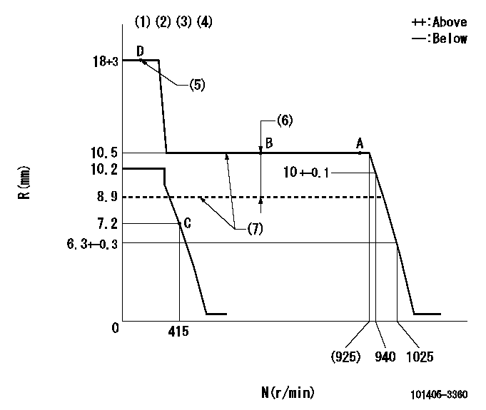
N:Pump speed
R:Rack position (mm)
(1)Target notch: K
(2)Tolerance for racks not indicated: +-0.05mm.
(3)The torque control spring does not operate.
(4)Adjust the secondary timing before adjusting the governor.
(5)When the hydraulic cylinder is OFF
(6)Boost compensator stroke: BCL
(7)When hydraulic cylinder ON: P1
----------
K=15 BCL=(1.6)mm P1=127+-10kPa(1.3+-0.1kgf/cm2)
----------
----------
K=15 BCL=(1.6)mm P1=127+-10kPa(1.3+-0.1kgf/cm2)
----------
Speed control lever angle
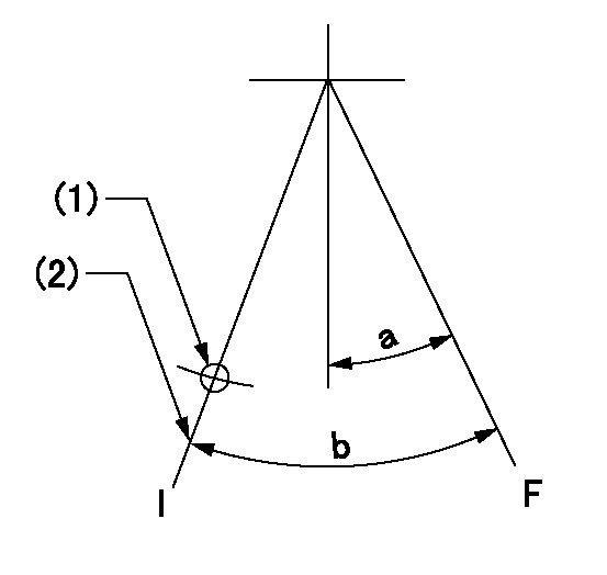
F:Full speed
I:Idle
(1)Use the hole at R = aa
(2)Stopper bolt setting
----------
aa=63mm
----------
a=5.5deg+-5deg b=20.5deg+-5deg
----------
aa=63mm
----------
a=5.5deg+-5deg b=20.5deg+-5deg
Stop lever angle
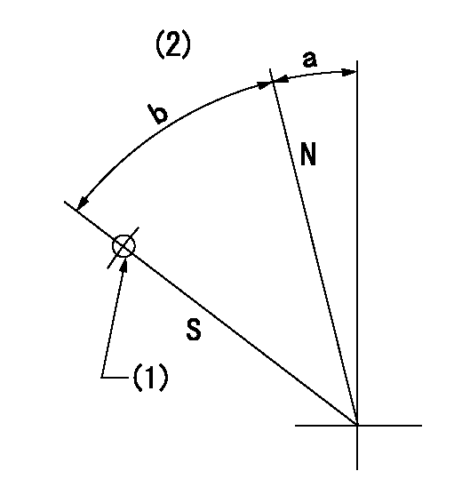
N:Pump normal
S:Stop the pump.
(1)Use the pin at R = aa
(2)No return spring
----------
aa=24mm
----------
a=0deg+-5deg b=53deg+-5deg
----------
aa=24mm
----------
a=0deg+-5deg b=53deg+-5deg
0000001501 TAMPER PROOF
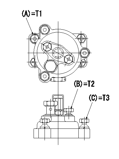
Tamperproofing-equipped boost compensator cover installation procedure
(1)After adjusting the governor and the boost compensator, tighten to the specified torque to break off the bolt heads.
(Tightening torque T = T1 maximum)
(2)After adjusting the governor and the boost compensator, tighten to the specified torque to break off the bolt heads.
(Tightening torque T = T2)
(3)After adjusting the governor and the boost compensator, tighten to the specified torque to break off the bolt heads.
(Tightening torque T = T3)
----------
T1=7.16~9.12N-m(0.73~0.93kgf-m) T2=2.9~4.4N-m(0.3~0.45kgf-m) T3=2.9~4.4N-m(0.3~0.45kgf-m)
----------
----------
T1=7.16~9.12N-m(0.73~0.93kgf-m) T2=2.9~4.4N-m(0.3~0.45kgf-m) T3=2.9~4.4N-m(0.3~0.45kgf-m)
----------
Timing setting
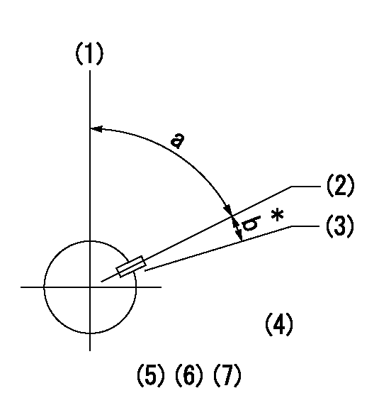
(1)Pump vertical direction
(2)Key groove position at No. 1 cylinder's beginning of injection position (at BTDC: aa).
(3)Position of the key groove of the No. 1 cylinder at B.T.D.C. bb (fix the governor flyweight at this position for delivery).
(4)B.T.D.C.: aa
(5)At second timing adjustment, set the camshaft at the * position and tighten the flyweight locknut.
(6)Align the flyweight's timing gear position with the lockpin groove and then fully tighten the flyweight to the camshaft.
(7)Remove the lock pin and adjust the governor. Reinstall the lock pin to fix the flyweight for delivery.
----------
aa=11deg bb=0deg
----------
a=54deg54min+-3deg b=5.5deg+-30min
----------
aa=11deg bb=0deg
----------
a=54deg54min+-3deg b=5.5deg+-30min
Information:
You must read and understand the warnings and instructions contained in the Safety section of this manual before performing any operation or maintenance procedures.Before proceeding with this maintenance interval, perform previous maintenance interval requirements. Perform the maintenance at the interval listed in the Maintenance Schedule for your engine.Engine Protection Devices
Inspect For Proper Operation
The engine protective alarm and shutoff controls must be tested, inspected and checked by an authorized Caterpillar dealer at least every year or 1000 hours for proper operation. The manual shutoff functions should be tested to ensure proper operation and protection to the engine. Refer to Engine Control, Monitoring and Protection in the Operation Section in this Manual.Have the checks made by a qualified mechanic. Consult your authorized Caterpillar engine dealer, or refer to the Service Manual for your engine.Verify Alarm and Shutdown Operation
Check for loose, broken, or damaged wiring or components. Check the condition of all sensors and wiring. Repair or replace any broken or malfunctioning sensors before they become a problem. The inspection only takes a few minutes and could avert a potential problem that could cause your engine to fail.Operational Checks
Start the engine. Use the starting procedure found in the Engine Starting topic in this publication.The operational checks are intended to check the engine starting and stopping, lubrication and fuel systems as well as overall operation. The checks should take no longer than five minutes to complete. Longer periods of operation are not required.Automatic Switches
Check that all switches are in proper position for automatic start.The shutoff controls must be checked so that they function properly when they are required. To prevent damage to the engine while performing the test, only authorized personnel or your Caterpillar dealer should perform the checks.Engine Valve Lash
Check/Adjust
Initial valve lash adjustment on new or rebuilt engines is recommended and should have been performed at the first normally scheduled oil change interval (125 Hours) due to initial wear and seating of valve train components. Subsequent adjustments should be made at every 1000 Hours.Set the valve lash clearance to the nominal value given in the chart shown in the Engine Specifications section. Refer to the information in the Every 125 Hour maintenance and the Service Manual for the procedure.Turbochargers
If the engine is operated until the component(s) fails, it could cause additional damage to the engine. Damage to the turbocharger compressor wheel could cause parts from the compressor wheel to enter the engine cylinder and cause additional damage to the piston, valve and cylinder head.Inspect for Proper Operation
Turbocharger bearing failures can cause large quantities of oil to enter the air inlet and exhaust systems. Loss of engine lubricant can result in serious engine damage.Minor leakage of a turbocharger housing under extended low idle operation will not cause problems as long as no turbocharger bearing failure occurred.When a turbocharger bearing failure is accompanied by a significant engine performance loss (exhaust smoke or engine speed up at no load), DO NOT continue engine operation until the turbocharger is repaired or replaced.
1. Remove the
Have questions with 101405-3360?
Group cross 101405-3360 ZEXEL
Komatsu
Komatsu
Komatsu
101405-3360
F 01G 000 00R
4063996
INJECTION-PUMP ASSEMBLY
SAA4D102
SAA4D102
101405-3360
F 01G 000 00R
6737711150
INJECTION-PUMP ASSEMBLY
SAA4D102
SAA4D102

