Information injection-pump assembly
BOSCH
9 400 613 040
9400613040
ZEXEL
101405-3300
1014053300
KOMATSU
4063745
4063745
Rating:
Service parts 101405-3300 INJECTION-PUMP ASSEMBLY:
1.
_

5.
AUTOM. ADVANCE MECHANIS
6.
COUPLING PLATE
7.
COUPLING PLATE
8.
_
9.
_
11.
Nozzle and Holder
4063212
12.
Open Pre:MPa(Kqf/cm2)
22.0{224}

15.
NOZZLE SET
Cross reference number
BOSCH
9 400 613 040
9400613040
ZEXEL
101405-3300
1014053300
KOMATSU
4063745
4063745
Zexel num
Bosch num
Firm num
Name
101405-3300
9 400 613 040
4063745 KOMATSU
INJECTION-PUMP ASSEMBLY
SAA4D102E K 14BC INJECTION PUMP ASSY PE4A,5A, PE
SAA4D102E K 14BC INJECTION PUMP ASSY PE4A,5A, PE
101405-3300
9 400 613 040
6737711220 KOMATSU
INJECTION-PUMP ASSEMBLY
SAA4D102E K 14BC INJECTION PUMP ASSY PE4A,5A, PE
SAA4D102E K 14BC INJECTION PUMP ASSY PE4A,5A, PE
Calibration Data:
Adjustment conditions
Test oil
1404 Test oil ISO4113 or {SAEJ967d}
1404 Test oil ISO4113 or {SAEJ967d}
Test oil temperature
degC
40
40
45
Nozzle and nozzle holder
105780-8140
Bosch type code
EF8511/9A
Nozzle
105780-0000
Bosch type code
DN12SD12T
Nozzle holder
105780-2080
Bosch type code
EF8511/9
Opening pressure
MPa
17.2
Opening pressure
kgf/cm2
175
Injection pipe
Outer diameter - inner diameter - length (mm) mm 6-2-600
Outer diameter - inner diameter - length (mm) mm 6-2-600
Overflow valve
131424-3420
Overflow valve opening pressure
kPa
255
221
289
Overflow valve opening pressure
kgf/cm2
2.6
2.25
2.95
Tester oil delivery pressure
kPa
255
255
255
Tester oil delivery pressure
kgf/cm2
2.6
2.6
2.6
Direction of rotation (viewed from drive side)
Right R
Right R
Injection timing adjustment
Direction of rotation (viewed from drive side)
Right R
Right R
Injection order
1-3-4-2
Pre-stroke
mm
2.7
2.65
2.75
Rack position
After adjusting injection quantity. R=A
After adjusting injection quantity. R=A
Beginning of injection position
Drive side NO.1
Drive side NO.1
Difference between angles 1
Cal 1-3 deg. 90 89.5 90.5
Cal 1-3 deg. 90 89.5 90.5
Difference between angles 2
Cal 1-4 deg. 180 179.5 180.5
Cal 1-4 deg. 180 179.5 180.5
Difference between angles 3
Cyl.1-2 deg. 270 269.5 270.5
Cyl.1-2 deg. 270 269.5 270.5
Injection quantity adjustment
Adjusting point
A
Rack position
9.2
Pump speed
r/min
1100
1100
1100
Average injection quantity
mm3/st.
93.5
92.5
94.5
Max. variation between cylinders
%
0
-2.5
2.5
Basic
*
Fixing the lever
*
Boost pressure
kPa
45.3
45.3
Boost pressure
mmHg
340
340
Hydraulic cylinder ON
*
Injection quantity adjustment_02
Adjusting point
-
Rack position
6.4+-0.5
Pump speed
r/min
485
485
485
Average injection quantity
mm3/st.
10
9
11
Max. variation between cylinders
%
0
-15
15
Fixing the rack
*
Boost pressure
kPa
0
0
0
Boost pressure
mmHg
0
0
0
Hydraulic cylinder ON
*
Remarks
Adjust only variation between cylinders; adjust governor according to governor specifications.
Adjust only variation between cylinders; adjust governor according to governor specifications.
Injection quantity adjustment_03
Adjusting point
E
Rack position
9.4++
Pump speed
r/min
100
100
100
Average injection quantity
mm3/st.
65
60
70
Fixing the lever
*
Boost pressure
kPa
0
0
0
Boost pressure
mmHg
0
0
0
Hydraulic cylinder OFF
*
Rack limit
*
Boost compensator adjustment
Pump speed
r/min
650
650
650
Rack position
R1-1
Boost pressure
kPa
10.7
8
13.4
Boost pressure
mmHg
80
60
100
Boost compensator adjustment_02
Pump speed
r/min
650
650
650
Rack position
R1-0.4
Boost pressure
kPa
20
18.7
21.3
Boost pressure
mmHg
150
140
160
Boost compensator adjustment_03
Pump speed
r/min
650
650
650
Rack position
R1(9.2)
Boost pressure
kPa
32
32
32
Boost pressure
mmHg
240
240
240
Test data Ex:
Governor adjustment
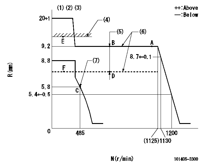
N:Pump speed
R:Rack position (mm)
(1)Target notch: K
(2)Tolerance for racks not indicated: +-0.05mm.
(3)Deliver without the torque control spring operating.
(4)RACK LIMIT (When hydraulic cylinder is OFF)
(5)Boost compensator stroke: BCL
(6)When hydraulic cylinder ON: P1
(7)Set idle sub-spring
----------
K=12 BCL=1+-0.1mm P1=127+-10kPa{1.3+-0.1kgf/cm2}
----------
----------
K=12 BCL=1+-0.1mm P1=127+-10kPa{1.3+-0.1kgf/cm2}
----------
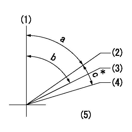
Speed control lever angle

F:Full speed
I:Idle
(1)Use the hole at R = aa
(2)Stopper bolt setting
----------
aa=74mm
----------
a=16deg+-5deg b=34deg+-5deg
----------
aa=74mm
----------
a=16deg+-5deg b=34deg+-5deg
Stop lever angle
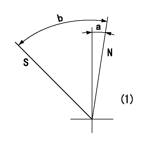
N:Pump normal
S:Stop the pump.
(1)No return spring
----------
----------
a=0deg+-5deg b=53deg+-5deg
----------
----------
a=0deg+-5deg b=53deg+-5deg
0000001501 I/P WITH LOAD PLUNGER ADJ
Adjusting procedure for load plunger equipped pump with RSV (cam lock) governor (see service information S.I. 434 for details).
At cam lift h+-0.01, set the camshaft c deg from the * mark in accordance with the timing adjustment procedure.
2. Align the flyweight's timing tooth position and the lock pin groove and then fully tighten the flyweight to the camshaft. Then, remove the lock pin.
3. Adjust the maximum variation between cylinders and injection quantity.
4. Adjust using the pre-stroke adjusting shim so that the pre-stroke value is the value for 4/4 load (standard point A).
5. After adjusting the pre-stroke, reconfirm that the injection quantity and the maximum variation between cylinders are as specified.
6. At delivery, again fix the flyweight using the lock pin.
----------
h=2.7mm c=5deg45min+-30min
----------
----------
h=2.7mm c=5deg45min+-30min
----------
0000001601 TAMPER PROOF
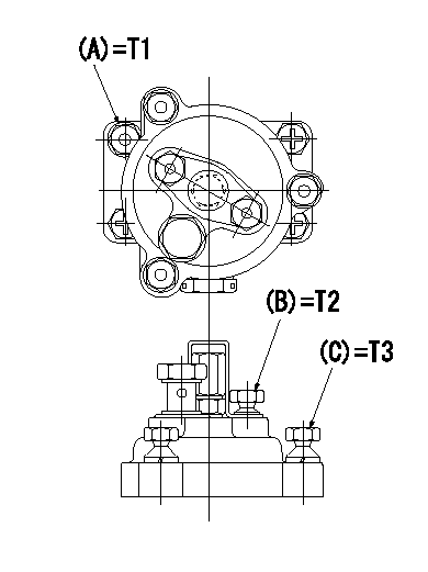
Tamperproofing-equipped boost compensator cover installation procedure
(1)After adjusting the governor and the boost compensator, tighten to the specified torque to break off the bolt heads.
(Tightening torque T = T1 maximum)
(2)After adjusting the governor and the boost compensator, tighten to the specified torque to break off the bolt heads.
(Tightening torque T = T2)
(3)After adjusting the governor and the boost compensator, tighten to the specified torque to break off the bolt heads.
(Tightening torque T = T3)
----------
T1=7.16~9.12N-m(0.73~0.93kgf-m) T2=2.9~4.4N-m(0.3~0.45kgf-m) T3=2.9~4.4N-m(0.3~0.45kgf-m)
----------
----------
T1=7.16~9.12N-m(0.73~0.93kgf-m) T2=2.9~4.4N-m(0.3~0.45kgf-m) T3=2.9~4.4N-m(0.3~0.45kgf-m)
----------
Timing setting
(1)Pump vertical direction
(2)Key groove position for No. 1 cylinder's cam lift h = cc (at BTDC aa).
(3)Key groove position for No. 1 cylinder's beginning of injection (at point A after injection quantity adjustment).
(4)Position of the key groove of the No. 1 cylinder at B.T.D.C. bb (fix the governor flyweight at this position for delivery).
(5)B.T.D.C.: aa
----------
aa=11.5deg bb=0deg cc=2.7+-0.01mm
----------
a=55deg48min+-3deg b=55deg48min+-3deg13min48sec c=5deg45min+-30min
----------
aa=11.5deg bb=0deg cc=2.7+-0.01mm
----------
a=55deg48min+-3deg b=55deg48min+-3deg13min48sec c=5deg45min+-30min
Information:
Proper operation and maintenance are key factors in obtaining the maximum life and economy of the engine. Normal operating temperatures are between -40°C (-40°F) and 120°C (248°F). Following the directions in this Manual will lower operating costs.The time needed for the engine to reach the normal mode of operation is usually less than the time taken for a walk-around inspection of the engine.After the engine is started and the cold low speed operation is completed, the engine can be operated at rated speed and low power. The engine will reach normal operating temperature faster when operated at low power demand than when idled at no load. Typically the engine should reach operating temperature in a few minutes.The electronic governor/control (ECM) system provides complete engine speed governing and controls cold start mode strategies, torque shaping, smoke limiting, system diagnostics and communication data links to monitor performance and diagnostic information. Warning outputs are provided for low oil pressure, low boost pressure, high coolant temperature and low coolant level with a diagnostic lamp.Electronic Control System Operation
The 3408 & 3412 electronically controlled governor functions like a mechanical governor in the mid-speed operating range. The governor has a programmable low idle rpm of 600 to 750 rpm, regardless of load. The governor eliminates most of the overrun at high idle that is experienced with a mechanical governor.During the cranking cycle, the safety shutoffs are inoperative, and will not allow a low oil pressure shut down. When oil pressure reaches a safe level, the safety circuit is armed by the arming relay. High water temperature or low oil pressure will now stop the engine and prevent major damage.If an unsafe engine condition exists, a sending unit completes the circuit to the safety relay and locking relay. The safety relay closes the fuel supply valve and the engine stops. The locking relay insures that the circuit to the safety relay is complete, even if the remote contacts open.Before restarting any unit which has been shut down by the safety circuit, the cause must be determined and corrected. The safety circuit must be reset by moving the start selector switch to the OFF position.Operating Driven Equipment Without Load
* Operate the engine at LOW IDLE. After normal oil pressure is reached and the jacket water temperature gauge begins to rise, the engine may be operated at full load.* If equipped with auxiliary driven equipment: To get the driven equipment in motion, use a smooth, easy engagement without increasing engine speed above low idle or slipping the clutch. Engage the clutch smoothly. It is not necessary to advance the throttle to get the driven equipment moving in most instances.
DO NOT allow the engine rpm to exceed 2450 rpm, or engine damage could result.Operation of the engine at 2450 rpm or above will cause the DIAGNOSTIC lamp to come on and a fault to be logged.
Operating Driven Equipment With Load
Always increase engine speed before increasing load.
1. Move the governor control lever to half engine speed. Begin operating the engine
Have questions with 101405-3300?
Group cross 101405-3300 ZEXEL
Komatsu
101405-3300
9 400 613 040
4063745
INJECTION-PUMP ASSEMBLY
SAA4D102E
SAA4D102E
101405-3300
9 400 613 040
6737711220
INJECTION-PUMP ASSEMBLY
SAA4D102E
SAA4D102E