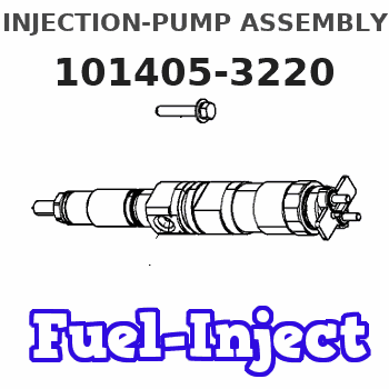
Information injection-pump assembly
BOSCH
9 400 614 057
9400614057
ZEXEL
101405-3220
1014053220
KOMATSU
3863983
3863983
Rating:
Include in #1:
101609-9173
as _
Cross reference number
BOSCH
9 400 614 057
9400614057
ZEXEL
101405-3220
1014053220
KOMATSU
3863983
3863983
Zexel num
Bosch num
Firm num
Name
9 400 614 057
3863983 KOMATSU
INJECTION-PUMP ASSEMBLY
S4D102E K 14BC INJECTION PUMP ASSY PE4A,5A, PE
S4D102E K 14BC INJECTION PUMP ASSY PE4A,5A, PE
9 400 614 057
6732711420 KOMATSU
INJECTION-PUMP ASSEMBLY
S4D102E K 14BC INJECTION PUMP ASSY PE4A,5A, PE
S4D102E K 14BC INJECTION PUMP ASSY PE4A,5A, PE
Calibration Data:
Adjustment conditions
Test oil
1404 Test oil ISO4113 or {SAEJ967d}
1404 Test oil ISO4113 or {SAEJ967d}
Test oil temperature
degC
40
40
45
Nozzle and nozzle holder
105780-8140
Bosch type code
EF8511/9A
Nozzle
105780-0000
Bosch type code
DN12SD12T
Nozzle holder
105780-2080
Bosch type code
EF8511/9
Opening pressure
MPa
17.2
Opening pressure
kgf/cm2
175
Injection pipe
Outer diameter - inner diameter - length (mm) mm 6-2-600
Outer diameter - inner diameter - length (mm) mm 6-2-600
Overflow valve
131424-3420
Overflow valve opening pressure
kPa
255
221
289
Overflow valve opening pressure
kgf/cm2
2.6
2.25
2.95
Tester oil delivery pressure
kPa
157
157
157
Tester oil delivery pressure
kgf/cm2
1.6
1.6
1.6
Direction of rotation (viewed from drive side)
Right R
Right R
Injection timing adjustment
Direction of rotation (viewed from drive side)
Right R
Right R
Injection order
1-3-4-2
Pre-stroke
mm
2.5
2.45
2.55
Beginning of injection position
Drive side NO.1
Drive side NO.1
Difference between angles 1
Cal 1-3 deg. 90 89.5 90.5
Cal 1-3 deg. 90 89.5 90.5
Difference between angles 2
Cal 1-4 deg. 180 179.5 180.5
Cal 1-4 deg. 180 179.5 180.5
Difference between angles 3
Cyl.1-2 deg. 270 269.5 270.5
Cyl.1-2 deg. 270 269.5 270.5
Injection quantity adjustment
Adjusting point
A
Rack position
9.7
Pump speed
r/min
1150
1150
1150
Average injection quantity
mm3/st.
97.5
96.5
98.5
Max. variation between cylinders
%
0
-2.5
2.5
Basic
*
Fixing the lever
*
Boost pressure
kPa
46.7
46.7
Boost pressure
mmHg
350
350
Hydraulic cylinder ON
*
Injection quantity adjustment_02
Adjusting point
-
Rack position
6.8+-0.5
Pump speed
r/min
475
475
475
Average injection quantity
mm3/st.
11.5
10.5
12.5
Max. variation between cylinders
%
0
-15
15
Fixing the rack
*
Boost pressure
kPa
0
0
0
Boost pressure
mmHg
0
0
0
Hydraulic cylinder ON
*
Remarks
Adjust only variation between cylinders; adjust governor according to governor specifications.
Adjust only variation between cylinders; adjust governor according to governor specifications.
Injection quantity adjustment_03
Adjusting point
E
Rack position
9.9++
Pump speed
r/min
100
100
100
Average injection quantity
mm3/st.
95
95
105
Fixing the lever
*
Boost pressure
kPa
0
0
0
Boost pressure
mmHg
0
0
0
Hydraulic cylinder OFF
*
Rack limit
*
Boost compensator adjustment
Pump speed
r/min
750
750
750
Rack position
R1-1.3
Boost pressure
kPa
13.3
10.6
16
Boost pressure
mmHg
100
80
120
Boost compensator adjustment_02
Pump speed
r/min
750
750
750
Rack position
R1(9.7)
Boost pressure
kPa
33.3
33.3
33.3
Boost pressure
mmHg
250
250
250
Test data Ex:
Governor adjustment
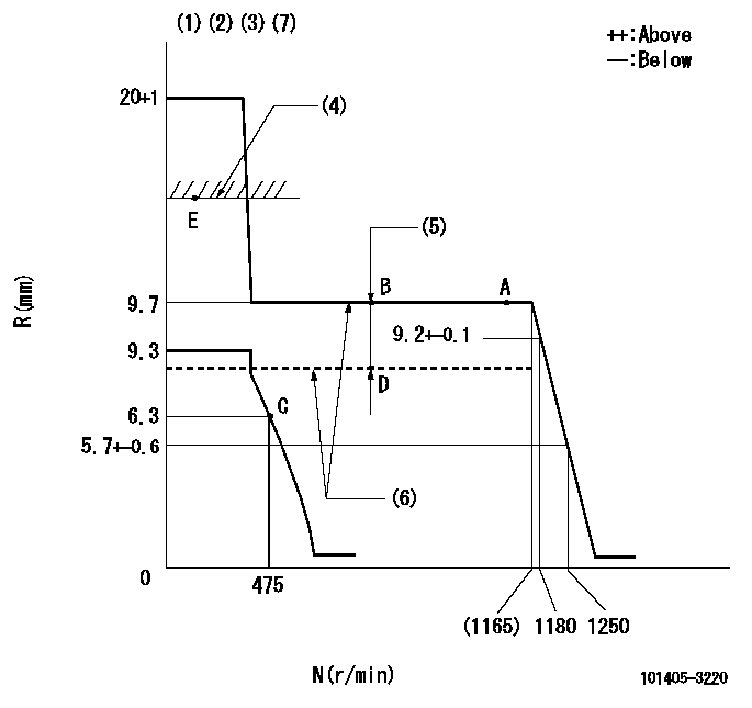
N:Pump speed
R:Rack position (mm)
(1)Target notch: K
(2)Tolerance for racks not indicated: +-0.05mm.
(3)Deliver without the torque control spring operating.
(4)RACK LIMIT (When hydraulic cylinder is OFF)
(5)Boost compensator stroke: BCL
(6)When hydraulic cylinder ON: P1
(7)Adjust the secondary timing before adjusting the governor.
----------
K=16 BCL=1.3+-0.1mm P1=((392)kPa{(4)kgf/cm2})
----------
----------
K=16 BCL=1.3+-0.1mm P1=((392)kPa{(4)kgf/cm2})
----------
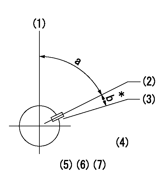
Speed control lever angle
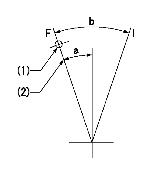
F:Full speed
I:Idle
(1)Use the hole at R = aa
(2)Stopper bolt setting
----------
aa=74mm
----------
a=20deg+-5deg b=36deg+-5deg
----------
aa=74mm
----------
a=20deg+-5deg b=36deg+-5deg
Stop lever angle
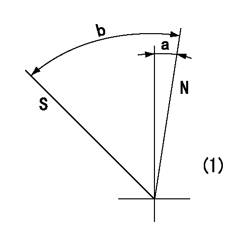
N:Pump normal
S:Stop the pump.
(1)No return spring
----------
----------
a=0deg+-5deg b=53deg+-5deg
----------
----------
a=0deg+-5deg b=53deg+-5deg
Timing setting
(1)Pump vertical direction
(2)Key groove position at No. 1 cylinder's beginning of injection position (at BTDC: aa).
(3)Position of the key groove of the No. 1 cylinder at B.T.D.C. bb (fix the governor flyweight at this position for delivery).
(4)B.T.D.C.: aa
(5)At second timing adjustment, set the camshaft at the * position and tighten the flyweight locknut.
(6)Align the flyweight's timing gear position with the lockpin groove and then fully tighten the flyweight to the camshaft.
(7)Remove the lock pin and adjust the governor. Reinstall the lock pin to fix the flyweight for delivery.
----------
aa=15deg bb=0deg
----------
a=54deg54min+-3deg b=7deg30min+-30min
----------
aa=15deg bb=0deg
----------
a=54deg54min+-3deg b=7deg30min+-30min
Information:
Caterpillar Reference Material
SEBD0518, Know Your Cooling SystemSEBD0970, Coolant and Your EngineSEHS7067, Fuels for Caterpillar Diesel EnginesSEHS8622, Using the FT1984 Air-To-Air Aftercooler Leak Test GroupSEHS8741, Using 8C5919 Service Program Module Operating ManualSEHS8743, Using 7X1830 Service Program Module Operating ManualSEHS8746, Using the 1U5540 Tool GroupSEHS8867, Using the 1U6661 Pop (Injector) TesterSEHS8884, Unit Injector Test SpecificationsLEDT5092, Driving Techniques For Maximum Fuel EconomyLEBT8121, Truck Engine Application and Installation GuideLEKQ3363, Caterpillar Engine Data Sheet 60.1 - "Fuels Recommended For Use In Caterpillar Truck Engines"SEBU6310, EMA Engine Oil Data BookSEBD0640, Oil and Your EngineSEBD0717, Diesel Fuels and Your EngineSEHS9031, Storage Procedure for Caterpillar ProductsSEBP1798, 3176 ATAAC Truck Engine Parts Manual (2YG1 and Up)SEBP1799, 3176 ATAAC Truck Engine Parts Manual (2YG1 and Up)SEBP1954, 3176 ATAAC Truck Engine Parts Manual (7LG1 and Up)SENR3910, 3176 ATAAC Truck Engine Service Manual (2YG1 and Up)SENR5105, 3176 ATAAC Truck Engine Service Manual (7LG1 and Up)SENR3912, 3176 ATAAC Truck Engine Schematic Manual (2YG1 and Up)SENR5111, 3176 ATAAC Truck Engine Schematic Manual (7LG1 and Up)SENR3913, 3176 ATAAC Truck Engine Electrical Manual (2YG1 and Up)SENR5112, 3176 ATAAC Truck Engine Electrical Manual (7LG1 and Up)SENR3616, 3176 ATAAC Truck Engine Troubleshooting Manual (2YG1 and Up)SENR5110, 3176 ATAAC Truck Engine Troubleshooting Manual (7LG1 and Up)SENR4248 3176 ATAAC Truck Engine Mechanical Manual (2YG1 and Up)SENR5113 3176 ATAAC Truck Engine Mechanical Manual (7LG1 and Up)SENR4249, 3176 ATAAC Truck Engine Performance Specifications (7LG1 and Up)SENR5114, 3176 ATAAC Truck Engine Performance Specifications (7LG1 and Up)SENR4250, 3176 ATAAC Truck Engine OEM Systems Manual (2YG1 and Up)SENR5115, 3176 ATAAC Truck Engine OEM Systems Manual (7LG1 and Up)SENR4251, 3176 ATAAC Truck Engine Jacobs Brake Manual (2YG1 and Up)SENR5116, 3176 ATAAC Truck Engine Jacobs Brake Manual (7LG1 and Up)SEBR0514, Low Emission systemSEBF8029, Index to Guidelines for Reusable Parts and Salvage OperationsSEBF8062, Guideline for Reusable Parts-Procedure to Inspect and Clean Air FiltersPEHP7504, CAT Engine Oil Spec SheetsPEHP7505, CAT Diesel Engine Oil Spec SheetsAll of the above publications are available through your Caterpillar dealer.Additional Reference Material
ASTM D2896 -TBN MeasurementsASTM D1384 -Glassware Corrosion TestASTM D2809 -Cavitation Corrosion of Aluminum TestASTM D4340 -Hot Surface Corrosion of Aluminum TestASTM Specs can normally be obtained from your local technilogical society, library or college.SAE J313 -Diesel FuelsSAE J754 -NomenclatureSAE J183 -ClassificationSAE Specs can be found in your SAE handbook or can be obtained from your local library, college or technilogical society.