Information injection-pump assembly
BOSCH
9 400 614 046
9400614046
ZEXEL
101405-3021
1014053021
KOMATSU
3863802
3863802
Rating:
Service parts 101405-3021 INJECTION-PUMP ASSEMBLY:
1.
_
5.
AUTOM. ADVANCE MECHANIS
6.
COUPLING PLATE
7.
COUPLING PLATE
8.
_
9.
_
10.
NOZZLE AND HOLDER ASSY
11.
Nozzle and Holder
12.
Open Pre:MPa(Kqf/cm2)
13.
NOZZLE-HOLDER
14.
NOZZLE
15.
NOZZLE SET
Cross reference number
BOSCH
9 400 614 046
9400614046
ZEXEL
101405-3021
1014053021
KOMATSU
3863802
3863802
Zexel num
Bosch num
Firm num
Name
9 400 614 046
3863802 KOMATSU
INJECTION-PUMP ASSEMBLY
S4D102E K 14BC INJECTION PUMP ASSY PE4A,5A, PE
S4D102E K 14BC INJECTION PUMP ASSY PE4A,5A, PE
9 400 614 046
6732711151 KOMATSU
INJECTION-PUMP ASSEMBLY
S4D102E K 14BC INJECTION PUMP ASSY PE4A,5A, PE
S4D102E K 14BC INJECTION PUMP ASSY PE4A,5A, PE
Calibration Data:
Adjustment conditions
Test oil
1404 Test oil ISO4113 or {SAEJ967d}
1404 Test oil ISO4113 or {SAEJ967d}
Test oil temperature
degC
40
40
45
Nozzle and nozzle holder
105780-8140
Bosch type code
EF8511/9A
Nozzle
105780-0000
Bosch type code
DN12SD12T
Nozzle holder
105780-2080
Bosch type code
EF8511/9
Opening pressure
MPa
17.2
Opening pressure
kgf/cm2
175
Injection pipe
Outer diameter - inner diameter - length (mm) mm 6-2-600
Outer diameter - inner diameter - length (mm) mm 6-2-600
Overflow valve
131424-3420
Overflow valve opening pressure
kPa
255
221
289
Overflow valve opening pressure
kgf/cm2
2.6
2.25
2.95
Tester oil delivery pressure
kPa
157
157
157
Tester oil delivery pressure
kgf/cm2
1.6
1.6
1.6
Direction of rotation (viewed from drive side)
Right R
Right R
Injection timing adjustment
Direction of rotation (viewed from drive side)
Right R
Right R
Injection order
1-3-4-2
Pre-stroke
mm
2.5
2.45
2.55
Beginning of injection position
Drive side NO.1
Drive side NO.1
Difference between angles 1
Cal 1-3 deg. 90 89.5 90.5
Cal 1-3 deg. 90 89.5 90.5
Difference between angles 2
Cal 1-4 deg. 180 179.5 180.5
Cal 1-4 deg. 180 179.5 180.5
Difference between angles 3
Cyl.1-2 deg. 270 269.5 270.5
Cyl.1-2 deg. 270 269.5 270.5
Injection quantity adjustment
Adjusting point
A
Rack position
10
Pump speed
r/min
950
950
950
Average injection quantity
mm3/st.
104.5
103.5
105.5
Max. variation between cylinders
%
0
-2.5
2.5
Basic
*
Fixing the lever
*
Boost pressure
kPa
50.7
50.7
Boost pressure
mmHg
380
380
Hydraulic cylinder ON
*
Injection quantity adjustment_02
Adjusting point
C
Rack position
7+-0.5
Pump speed
r/min
460
460
460
Average injection quantity
mm3/st.
10.5
9.5
11.5
Max. variation between cylinders
%
0
-15
15
Fixing the rack
*
Boost pressure
kPa
0
0
0
Boost pressure
mmHg
0
0
0
Hydraulic cylinder ON
*
Injection quantity adjustment_03
Adjusting point
D
Rack position
-
Pump speed
r/min
100
100
100
Average injection quantity
mm3/st.
85
85
95
Fixing the lever
*
Boost pressure
kPa
0
0
0
Boost pressure
mmHg
0
0
0
Hydraulic cylinder OFF
*
Rack limit
*
Boost compensator adjustment
Pump speed
r/min
650
650
650
Rack position
R1-0.75
Boost pressure
kPa
23.3
20.6
26
Boost pressure
mmHg
175
155
195
Boost compensator adjustment_02
Pump speed
r/min
650
650
650
Rack position
R1(10)
Boost pressure
kPa
37.3
37.3
37.3
Boost pressure
mmHg
280
280
280
Test data Ex:
Governor adjustment
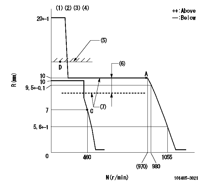
N:Pump speed
R:Rack position (mm)
(1)Target notch: K
(2)Tolerance for racks not indicated: +-0.05mm.
(3)The torque control spring does not operate.
(4)Adjust the secondary timing before adjusting the governor.
(5)RACK LIMIT (When hydraulic cylinder is OFF)
(6)Boost compensator stroke: BCL
(7)When hydraulic cylinder ON: P1
----------
K=8 BCL=0.75+-0.1mm P1=((392)kPa{(4)kgf/cm2})
----------
----------
K=8 BCL=0.75+-0.1mm P1=((392)kPa{(4)kgf/cm2})
----------
Speed control lever angle
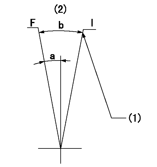
F:Full speed
I:Idle
(1)Stopper bolt setting
(2)Use the center hole at R = aa
----------
aa=80mm
----------
a=5deg+-3deg b=28deg+-5deg
----------
aa=80mm
----------
a=5deg+-3deg b=28deg+-5deg
Stop lever angle
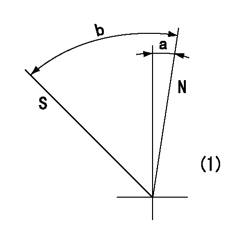
N:Pump normal
S:Stop the pump.
(1)No return spring
----------
----------
a=0deg+-5deg b=53deg+-5deg
----------
----------
a=0deg+-5deg b=53deg+-5deg
Timing setting
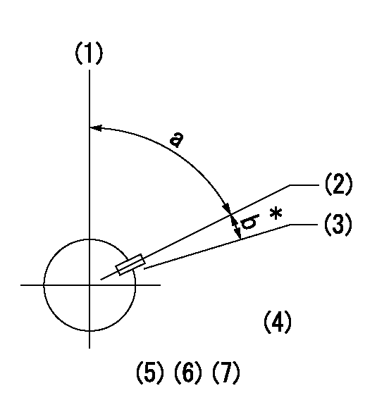
(1)Pump vertical direction
(2)Key groove position at No. 1 cylinder's beginning of injection position (at BTDC: aa).
(3)Position of the key groove of the No. 1 cylinder at B.T.D.C. bb (fix the governor flyweight at this position for delivery).
(4)B.T.D.C.: aa
(5)At second timing adjustment, set the camshaft at the * position and tighten the flyweight locknut.
(6)Align the flyweight's timing gear position with the lockpin groove and then fully tighten the flyweight to the camshaft.
(7)Remove the lock pin and adjust the governor. Reinstall the lock pin to fix the flyweight for delivery.
----------
aa=14deg bb=0deg
----------
a=54deg54min+-3deg b=7deg+-30min
----------
aa=14deg bb=0deg
----------
a=54deg54min+-3deg b=7deg+-30min
Information:
* When operating the vehicle downhill, do not coast or put the transmission in NEUTRAL.* Select the correct gear that does not allow the engine speed (rpm) to exceed the limits above and use the engine retarder and/or brakes to limit the speed of the truck.* A simple rule to follow is to select the same gear that would be required to go up the hill. However, DO NOT allow the engine to overspeed.For more information on economical operation of this engine, refer to form LEDT5092, Driving Techniques for Maximum Fuel Economy.Programmable Features
The 3176 has the programmable features of cruise control, PTO governing, vehicle speed limiting, high gears rpm limiting, low gears rpm limiting, TEL rpm limiting, idle shutdown timer and retarder coast/latch included in its functions.Cruise Control
Typical InstallationCruise control reduces driver fatigue and improves vehicle ride by eliminating throttle bounce. Cruise control can also reduce fuel consumption and driver to driver variations in a large fleet.* Vehicle speed MUST be ABOVE the low cruise control speed limit [typically 30 mph (48 km/h)].* Set the ON/OFF switch to the ON position.* Accelerate vehicle to desired speed.* Move the SET/RESUME switch momentarily into the SET position. The engine will maintain the speed that the truck is traveling when the SET switch is released. If the SET switch is held for more than one second, the truck speed will continue to increase until the SET switch is released. The cruise speed will then be set to the speed the truck is traveling when the SET switch is released.* Move the ON/OFF switch to the OFF position, or ...* Depress the clutch pedal, or ...* Depress the service brake pedal.* Return the ON/OFF switch to the ON position, and/or ...* Move the SET/RESUME switch momentarily into the RESUME position. The 3176 system remembers the last cruise control set speed as long as the engine is running.If the RESUME switch is held for more than one second, the 3176 will decrease the truck speed and a new set speed will be established when the RESUME switch is released.The throttle can be used to exceed the cruise control set speed, if the high cruise limit is lower than the vehicle speed limit. Releasing the throttle will return the truck to the previous cruise speed. The throttle override can be used to anticipate hills or for passing situations.To shift gears, the ON/OFF switch can be moved to the OFF position or disengage the clutch to deactivate the cruise control.After shifting gears, the cruise control can be reactivated by moving the ON/OFF switch to the ON position and/or momentarily setting the SET/RESUME switch in the RESUME position. The 3176 system may have a maximum cruise speed which has been specified by the owner of the truck. The cruise control will only function between the programmed Low Cruise Control Limit (LCC) and High Cruise Control Limit (HCC). The High Cruise Control set limit is also generally set at a lower mph (km/h) than the vehicle speed
