Information injection-pump assembly
BOSCH
9 400 610 442
9400610442
ZEXEL
101402-3812
1014023812
KOMATSU
3863347
3863347
Rating:
Compare Prices: .
As an associate, we earn commssions on qualifying purchases through the links below
$220.59
01 Dec 2024
0.8818[0.40] pounds
CN: zhengzhoujingjinglai
HGDSXZ Compatible Steering Cylinder Hydraulic Hose Line Kit 21548739 Compatible with Models 3863347 3863405 3863406 3863407
HGDSXZ Durability This hydraulic hose line kit is built Compatible With performance under various conditions. || Compatibility Designed to fit specific steering cylinder models without any modifications needed. || Efficiency Enhances steering responsiveness Compatible With a smoother and more controlled driving experience. || Installation Easy installation process with no special tools required Compatible With hassle-free setup. || Reliability Provides consistent hydraulic pressure Compatible With improved maneuverability and control. || Versatility Suitable Compatible With various applications, making it a great choice Compatible With different steering systems. || Maintenance Simple maintenance ensures longevity, allowing Compatible With reliable over time.
HGDSXZ Durability This hydraulic hose line kit is built Compatible With performance under various conditions. || Compatibility Designed to fit specific steering cylinder models without any modifications needed. || Efficiency Enhances steering responsiveness Compatible With a smoother and more controlled driving experience. || Installation Easy installation process with no special tools required Compatible With hassle-free setup. || Reliability Provides consistent hydraulic pressure Compatible With improved maneuverability and control. || Versatility Suitable Compatible With various applications, making it a great choice Compatible With different steering systems. || Maintenance Simple maintenance ensures longevity, allowing Compatible With reliable over time.
$164.77
24 Sep 2024
2.2046[0.99] pounds
CA: Grove_Distribution
Steering Cylinder Hose Kit Compatible with Volvo Penta DPR-B includes 4 Compatible with Hydraulic hoses
Generic 1232-08
Generic 1232-08
Service parts 101402-3812 INJECTION-PUMP ASSEMBLY:
1.
_
5.
AUTOM. ADVANCE MECHANIS
6.
COUPLING PLATE
7.
COUPLING PLATE
8.
_
9.
_
10.
NOZZLE AND HOLDER ASSY
11.
Nozzle and Holder
12.
Open Pre:MPa(Kqf/cm2)
21.6{220}
13.
NOZZLE-HOLDER
14.
NOZZLE
15.
NOZZLE SET
Cross reference number
BOSCH
9 400 610 442
9400610442
ZEXEL
101402-3812
1014023812
KOMATSU
3863347
3863347
Zexel num
Bosch num
Firm num
Name
101402-3812
9 400 610 442
3863347 KOMATSU
INJECTION-PUMP ASSEMBLY
S4D102E K 14BE INJECTION PUMP ASSY PE6A PE
S4D102E K 14BE INJECTION PUMP ASSY PE6A PE
101402-3812
9 400 610 442
6732711150 KOMATSU
INJECTION-PUMP ASSEMBLY
S4D102E K 14BE INJECTION PUMP ASSY PE6A PE
S4D102E K 14BE INJECTION PUMP ASSY PE6A PE
Calibration Data:
Adjustment conditions
Test oil
1404 Test oil ISO4113 or {SAEJ967d}
1404 Test oil ISO4113 or {SAEJ967d}
Test oil temperature
degC
40
40
45
Nozzle and nozzle holder
105780-8140
Bosch type code
EF8511/9A
Nozzle
105780-0000
Bosch type code
DN12SD12T
Nozzle holder
105780-2080
Bosch type code
EF8511/9
Opening pressure
MPa
17.2
Opening pressure
kgf/cm2
175
Injection pipe
Outer diameter - inner diameter - length (mm) mm 6-2-600
Outer diameter - inner diameter - length (mm) mm 6-2-600
Overflow valve
131424-3420
Overflow valve opening pressure
kPa
255
221
289
Overflow valve opening pressure
kgf/cm2
2.6
2.25
2.95
Tester oil delivery pressure
kPa
157
157
157
Tester oil delivery pressure
kgf/cm2
1.6
1.6
1.6
Direction of rotation (viewed from drive side)
Right R
Right R
Injection timing adjustment
Direction of rotation (viewed from drive side)
Right R
Right R
Injection order
1-3-4-2
Pre-stroke
mm
2.5
2.45
2.55
Beginning of injection position
Drive side NO.1
Drive side NO.1
Difference between angles 1
Cal 1-3 deg. 90 89.5 90.5
Cal 1-3 deg. 90 89.5 90.5
Difference between angles 2
Cal 1-4 deg. 180 179.5 180.5
Cal 1-4 deg. 180 179.5 180.5
Difference between angles 3
Cyl.1-2 deg. 270 269.5 270.5
Cyl.1-2 deg. 270 269.5 270.5
Injection quantity adjustment
Adjusting point
A
Rack position
10.4
Pump speed
r/min
950
950
950
Average injection quantity
mm3/st.
117
116
118
Max. variation between cylinders
%
0
-2.5
2.5
Basic
*
Fixing the lever
*
Boost pressure
kPa
44
44
Boost pressure
mmHg
330
330
Hydraulic cylinder ON
*
Injection quantity adjustment_02
Adjusting point
C
Rack position
7.2+-0.5
Pump speed
r/min
450
450
450
Average injection quantity
mm3/st.
14.5
13.5
15.5
Max. variation between cylinders
%
0
-15
15
Fixing the rack
*
Boost pressure
kPa
0
0
0
Boost pressure
mmHg
0
0
0
Hydraulic cylinder ON
*
Injection quantity adjustment_03
Adjusting point
D
Rack position
-
Pump speed
r/min
100
100
100
Average injection quantity
mm3/st.
90
90
100
Fixing the lever
*
Boost pressure
kPa
0
0
0
Boost pressure
mmHg
0
0
0
Hydraulic cylinder OFF
*
Rack limit
*
Boost compensator adjustment
Pump speed
r/min
650
650
650
Rack position
R1-0.25
Boost pressure
kPa
26
23.3
28.7
Boost pressure
mmHg
195
175
215
Boost compensator adjustment_02
Pump speed
r/min
650
650
650
Rack position
R1(10.4)
Boost pressure
kPa
30.7
30.7
30.7
Boost pressure
mmHg
230
230
230
Test data Ex:
Governor adjustment
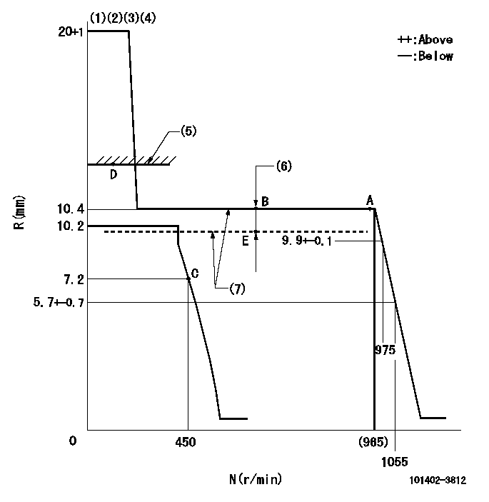
N:Pump speed
R:Rack position (mm)
(1)Target notch: K
(2)Tolerance for racks not indicated: +-0.05mm.
(3)The torque control spring does not operate.
(4)Adjust the secondary timing before adjusting the governor.
(5)RACK LIMIT (When hydraulic cylinder is OFF)
(6)Boost compensator stroke: BCL
(7)When the hydraulic cylinder is ON (P1)
----------
K=7 BCL=0.25+-0.1mm P1=((392)kPa{(4)kgf/cm2})
----------
----------
K=7 BCL=0.25+-0.1mm P1=((392)kPa{(4)kgf/cm2})
----------
Speed control lever angle
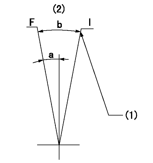
F:Full speed
I:Idle
(1)Stopper bolt setting
(2)Use the center hole at R = aa
----------
aa=80mm
----------
a=3deg+-3deg b=27deg+-5deg
----------
aa=80mm
----------
a=3deg+-3deg b=27deg+-5deg
Stop lever angle
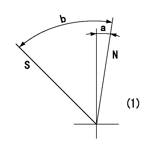
N:Pump normal
S:Stop the pump.
(1)Without return spring
----------
----------
a=0deg+-5deg b=53deg+-5deg
----------
----------
a=0deg+-5deg b=53deg+-5deg
Timing setting
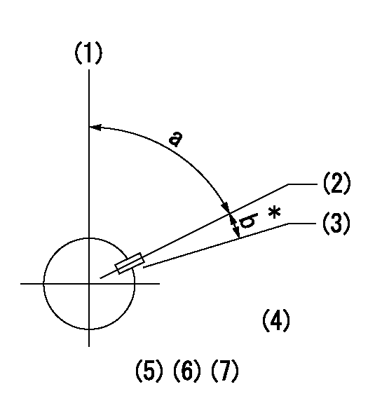
(1)Pump vertical direction
(2)Key groove position at No. 1 cylinder's beginning of injection position (at BTDC: aa).
(3)Position of the key groove of the No. 1 cylinder at B.T.D.C. bb (fix the governor flyweight at this position for delivery).
(4)B.T.D.C.: aa
(5)At second timing adjustment, set the camshaft at the * position and tighten the flyweight locknut.
(6)Align the flyweight's timing gear position with the lockpin groove and then fully tighten the flyweight to the camshaft.
(7)Remove the lock pin and adjust the governor. Reinstall the lock pin to fix the flyweight for delivery.
----------
aa=15deg bb=0deg
----------
a=54deg54min+-3deg b=7deg30min+-30min
----------
aa=15deg bb=0deg
----------
a=54deg54min+-3deg b=7deg30min+-30min
Information:
Solution
Do not operate or work on this product unless you have read and understood the instruction and warnings in the relevant Operation and Maintenance Manuals and relevant service literature. Failure to follow the instructions or heed the warnings could result in injury or death. Proper care is your responsibility.
Note: Only perform these troubleshooting steps when the DEF tank is fully thawed and there is no remaining ice crystals/slush in the tank.Note: If any of the troubleshooting indicates the replacement of the DEF manifold, do not replace the DEF manifold. Repair the DEF manifold using the DEF manifold sensor kit.
Use the electronic service tool to download a full Product Status Report (PSR) (including all histograms and histories) before performing any troubleshooting.
Review the PSR to determine which code/events recorded have led to the activation SCR inducement codes:Note: Check the "Aftertreatment Abnormal Shutdown History" for Hot/Cold Shutdown events which may have occurred prior to the current inducement situation and may be an indication the system was incorrectly shut down previously.
A Cold Shutdown is recorded when the ambient temp is below −5° C (23° F) and the system has not completed the cooldown and system purge during the previous key-cycle.
Only investigate a logged 1235-9 (5856-9) code if the code has occurred less than 5 hours prior to the current diagnostic clock value. If the code is not persistent, the code is likely to be generated by either old engine software or a power supply dropping below the min supply voltage. If the code is showing a persistent triggering when on the latest engine software, this condition would indicate a hardware/connection issue.
DEF level codes (1761-xx/E954) are not to be considered a sign of DEF Manifold hardware failure (especially when in low ambient temperatures) unless the codes remain persistent after a tank fill. If there is another code present such as 1761-2/3130-2 (DEF level – Erratic) or 5392-31/E1370 (DEF Loss of Prime), this condition would indicate a system level issue, or the DEF tank has recently been fully drained down for an extended period and may require time for any DEF deposits to dissolve before level readings stabilize.
The order of troubleshooting codes should be SCR Inducement last, with DEF Tank Level codes second from last, always troubleshooting the DEF Volume Erratic (1761-2/3130-2) or DEF – Loss of Prime (5392-31/E1370) codes first.
Prior to beginning any troubleshooting of the codes reviewed in Step 2 and based on analysis, check that the coolant diverter valve is functioning correctly. Not allowing a small coolant flow to heat DEF tank fluid unintentionally above ambient temperature without triggering any codes, refer to Troubleshooting, DEF Tank Temperature Is High.
Ensure that the coolant flow direction is aligned with the flow direction arrow valve on the valve body. Refer to Step 3civ.
Record the ambient air temperature and DEF tank fluid temperature prior to starting the engine. Use these temperature readings as the reference for determining a temperature increase after warming the engine at idle. Refer to Step6.Note: As DEF is used as the
Have questions with 101402-3812?
Group cross 101402-3812 ZEXEL
Komatsu
Komatsu
101402-3812
9 400 610 442
3863347
INJECTION-PUMP ASSEMBLY
S4D102E
S4D102E
101402-3812
9 400 610 442
6732711150
INJECTION-PUMP ASSEMBLY
S4D102E
S4D102E


