Information fuel-injection pump
BOSCH
9 410 617 260
9410617260
ZEXEL
104286-2030
1042862030
NIIGATA-TEKKOU
15E47003A
15e47003a

Rating:
Components :
| 0. | INJECTION-PUMP ASSEMBLY | 104286-2030 |
| 1. | _ | |
| 2. | FUEL INJECTION PUMP | |
| 3. | NUMBER PLATE | |
| 4. | _ | |
| 5. | CAPSULE | |
| 6. | ADJUSTING DEVICE | |
| 7. | NOZZLE AND HOLDER ASSY | |
| 8. | Nozzle and Holder | |
| 9. | Open Pre:MPa(Kqf/cm2) | |
| 10. | NOZZLE-HOLDER | |
| 11. | NOZZLE |
Scheme ###:
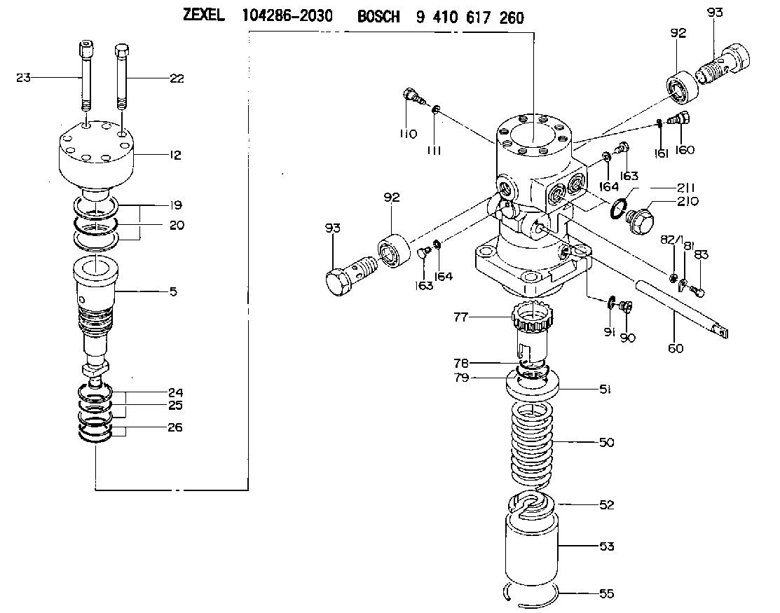
| 1. | [1] | 141055-6100 | PUMP HOUSING |
| 5. | [1] | 141188-0023 | PLUNGER-AND-BARREL ASSY |
| 12. | [1] | 141145-1220 | DELIVERY-VALVE ASSEMBLY |
| 19. | [2] | 016420-1050 | BACKUP RING |
| 20. | [1] | 141118-3300 | O-RING |
| 22. | [6] | 141124-5200 | BLEEDER SCREW |
| 23. | [2] | 141124-5300 | BLEEDER SCREW |
| 24. | [2] | 016420-0850 | BACKUP RING |
| 25. | [1] | 141118-3100 | O-RING |
| 26. | [2] | 141485-2600 | O-RING |
| 50. | [1] | 141215-8800 | COMPRESSION SPRING |
| 51. | [1] | 141216-7000 | SLOTTED WASHER |
| 52. | [1] | 141217-9300 | SLOTTED WASHER |
| 53. | [1] | 141294-0601 | GUIDE |
| 55. | [1] | 141220-3100 | LOCKING WASHER |
| 60. | [1] | 141291-3100 | CONTROL RACK |
| 77. | [1] | 141292-2400 | CONTROL SLEEVE |
| 78. | [1] | 141485-1001 | O-RING |
| 79. | [1] | 141118-3002 | O-RING |
| 81. | [1] | 141245-3200 | POINTER |
| 82/1. | [0] | 023500-6210 | PLAIN WASHER D11&6.4T1.5 |
| 82/1. | [0] | 029300-6010 | PLAIN WASHER D11&6.4T0.8 |
| 82/1. | [0] | 029300-6020 | PLAIN WASHER D11&6.4T0.35 |
| 83. | [1] | 020006-1440 | BLEEDER SCREW M6P1L14 |
| 90. | [1] | 029112-6020 | CAPSULE |
| 91. | [1] | 141403-1600 | GASKET |
| 92. | [2] | 141401-6100 | BUSHING |
| 92. | [2] | 141401-6100 | BUSHING |
| 93. | [2] | 141402-7200 | EYE BOLT |
| 93. | [2] | 141402-7200 | EYE BOLT |
| 110. | [1] | 141418-3701 | SET OF NUTS |
| 111. | [1] | 150934-1000 | GASKET |
| 160. | [1] | 141418-3701 | SET OF NUTS |
| 161. | [1] | 150934-1000 | GASKET |
| 163. | [2] | 029111-2020 | CAPSULE |
| 163. | [2] | 029111-2020 | CAPSULE |
| 164. | [2] | 026512-1840 | GASKET D17.9&12.2T1.50 |
| 164. | [2] | 026512-1840 | GASKET D17.9&12.2T1.50 |
| 210. | [2] | 141405-4801 | CAPSULE |
| 211. | [2] | 141485-3900 | O-RING |
Cross reference number
Zexel num
Bosch num
Firm num
Name
9 410 617 260
15E47003A NIIGATA-TEKKOU
FUEL-INJECTION PUMP
* K 24KV PF-1EV PF
* K 24KV PF-1EV PF
Information:
Installation of Oil Seal Case (Option)
(1) Coat the outside surface of the oil seal with engine oil.(2) Install the oil seal on the oil seal case.(3) Coat the lip of the oil seal with engine oil.(4) Install the O-ring into the oil seal case, and install the oil seal case on the flywheel housing. The oil seal case must be installed with the "Q" mark facing up.(5) Secure the oil seal case with the bolts.
Installation of oil seal case (option)Installation of Flywheel
(1) Install the flywheel to the crankshaft by aligning the hole with the dowel pin on the back-end of the crankshaft.(2) Place the washer and tighten the four bolts to the specified torque.
Installation of flywheelMeasurement of Flywheel Runout
Measure the flywheel runout with the flywheel installed to the crankshaft. If the standard value is exceeded, check the bolts for tightening condition and the mounting face for adhesion of foreign particles.
Measurement of face runout and circular runoutCylinder Head and Valve Mechanisms
Installation of Valve Stem Seal
(1) Apply engine oil to the valve stem, and insert it into the valve guide.(2) Place a new stem seal on the valve guide.(3) Using the stem seal installer, install the stem seal to the valve guide, making use of the valve stem as a guide.
Installation of valve stem sealInstallation of Valves and Valve Springs
(1) Place the valve spring and retainer on the valve guide, and install the valve cotter using the valve spring pusher.
Excessive compression of the valve spring can cause the retainer to contact the stem seal and damage the seal.
Installation of valve and valve spring(2) Using a soft-faced hammer, tap the top of the valve stem several times to make sure that the spring and valve cotter are securely installed.
Confirmation of secure valve cotter installationInstallation of Cylinder Head Gasket
(1) Make sure that the top face of the crankcase and piston upper surfaces are clean and free of dust.(2) Place a new gasket of the crankcase, making sure that the dowel pins on the top face of the crankcase enter the holes in the gasket.
Do not use a liquid gasket.
Installation of cylinder head gasketInstallation of Cylinder Head
Place the cylinder head on the head gasket, making sure that the dowel pins on the top face of the crankcase enters the holes in the cylinder head.
Installation of cylinder headTightening of Cylinder Head Bolts
Tighten the cylinder head bolts, following the tightening sequence shown in the diagram two or three times before reaching the specified torque.
Cylinder head bolt tightening sequenceAssembly of Rocker Arm and Rocker Shaft Assembly
When installing the rocker arms, make sure that the shaft assembly marks face the front of the engine, as shown in the diagram. After the assembly, make sure that the rocker arms move smoothly.
Assembly of rocker shaft assemblyInstallation of Pushrods
(1) Insert the pushrods in the cylinder head through the pushrod holes.(2) Make sure that the ball end of each pushrod rests securely on the curved surface of the tappet.Installation of Rocker Shaft Assemblies
(1) Install the valve caps.(2) Tighten the rocker shaft