Information fuel-injection pump
BOSCH
9 410 618 326
9410618326
ZEXEL
104286-2041
1042862041
NIIGATA-TEKKOU
15E47004C
15e47004c
Rating:
Components :
| 0. | INJECTION-PUMP ASSEMBLY | 104286-2041 |
| 1. | _ | |
| 2. | FUEL INJECTION PUMP | |
| 3. | NUMBER PLATE | |
| 4. | _ | |
| 5. | CAPSULE | |
| 6. | ADJUSTING DEVICE | |
| 7. | NOZZLE AND HOLDER ASSY | |
| 8. | Nozzle and Holder | |
| 9. | Open Pre:MPa(Kqf/cm2) | |
| 10. | NOZZLE-HOLDER | |
| 11. | NOZZLE |
Scheme ###:
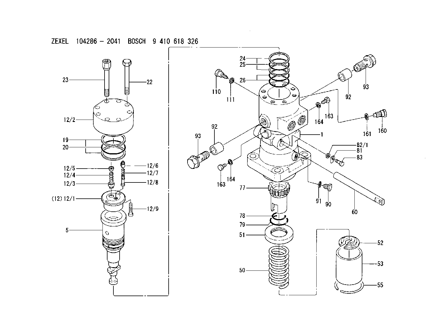
| 1. | [1] | 141055-5800 | PUMP HOUSING |
| 5. | [1] | 141188-0023 | PLUNGER-AND-BARREL ASSY |
| 12. | [1] | 141145-1220 | DELIVERY-VALVE ASSEMBLY |
| 12/1. | [1] | 141146-0400 | SEAT;D.V. |
| 12/2. | [1] | 141137-8700 | FITTING |
| 12/3. | [1] | 141145-1200 | DELIVERY-VALVE ASSEMBLY |
| 12/4. | [1] | 141144-0900 | COMPRESSION SPRING |
| 12/5. | [1] | 141113-4100 | SLOTTED WASHER |
| 12/6. | [1] | 141145-1300 | VALVE BODY |
| 12/7. | [1] | 141144-1000 | COMPRESSION SPRING |
| 12/8. | [1] | 141113-4200 | FILLER PIECE |
| 12/9. | [2] | 010206-2020 | HEX-SOCKET-HEAD CAP SCREW |
| 19. | [2] | 016420-1050 | BACKUP RING |
| 20. | [1] | 141118-3300 | O-RING |
| 22. | [6] | 141124-5200 | BLEEDER SCREW |
| 23. | [2] | 141124-5300 | BLEEDER SCREW |
| 24. | [2] | 016420-0850 | BACKUP RING |
| 25. | [1] | 141118-3100 | O-RING |
| 26. | [2] | 141485-2600 | O-RING |
| 50. | [1] | 141215-8801 | COMPRESSION SPRING |
| 51. | [1] | 141216-7000 | SLOTTED WASHER |
| 52. | [1] | 141217-9300 | SLOTTED WASHER |
| 53. | [1] | 141294-0601 | GUIDE |
| 55. | [1] | 141220-3100 | LOCKING WASHER |
| 60. | [1] | 141291-3100 | CONTROL RACK |
| 77. | [1] | 141292-2400 | CONTROL SLEEVE |
| 78. | [1] | 141485-1002 | O-RING |
| 79. | [1] | 141118-3002 | O-RING |
| 81. | [1] | 141245-3200 | POINTER |
| 82/1. | [0] | 023500-6210 | PLAIN WASHER D11&6.4T1.5 |
| 82/1. | [0] | 029300-6010 | PLAIN WASHER D11&6.4T0.8 |
| 82/1. | [0] | 029300-6020 | PLAIN WASHER D11&6.4T0.35 |
| 83. | [1] | 020006-1440 | BLEEDER SCREW M6P1L14 |
| 90. | [1] | 029112-6020 | CAPSULE |
| 91. | [1] | 141403-1600 | GASKET |
| 92. | [2] | 141401-6100 | BUSHING |
| 92. | [2] | 141401-6100 | BUSHING |
| 93. | [2] | 141402-7200 | EYE BOLT |
| 93. | [2] | 141402-7200 | EYE BOLT |
| 110. | [1] | 141418-3701 | SET OF NUTS |
| 111. | [1] | 150934-1000 | GASKET |
| 160. | [1] | 141418-3701 | SET OF NUTS |
| 161. | [1] | 150934-1000 | GASKET |
| 163. | [2] | 029111-2020 | CAPSULE |
| 163. | [2] | 029111-2020 | CAPSULE |
| 164. | [2] | 026512-1840 | GASKET D17.9&12.2T1.50 |
| 164. | [2] | 026512-1840 | GASKET D17.9&12.2T1.50 |
Cross reference number
Zexel num
Bosch num
Firm num
Name
104286-2041
15E47004C NIIGATA-TEKKOU
FUEL-INJECTION PUMP
K 24KX FUEL INJECTION PUMP PF-EX PF
K 24KX FUEL INJECTION PUMP PF-EX PF
Information:
Oil Pump
Disassembly and Inspection of Oil Pump
Measurement of Clearance Between Outer Rotor and Inner Rotor
Measure the clearance between the outer rotor and inner rotor, and, if the limit value is exceeded, replace the pump assembly.
Measurement of clearance between outer rotor and inner rotorMeasurement of Rotor and Case End Play
Measure the rotor and case end play, and, if the limit value is exceeded, replace the pump assembly.
Measurement of rotor and cover end playMeasurement of Clearance Between Outer Rotor and Pump Case
Measure the clearance between the outer rotor and pump case, and, if the limit value is exceeded, replace the pump assembly.
Measure the clearance between the outer rotor and caseReassembly of Oil Pump
Install the outer rotor to the pump case, check alignment mark (indentations) on the pump case cover, and then tighten the bolts. If the alignment marks are not aligned during the reassembly, the pump will not suck oil.
Alignment marks on pump case and pump case coverOil Filter and Oil Cooler
Inspection of Oil Filter, Oil Cooler and Relief Valve
Adjustment of Relief Valve
(1) Check the relief valve and valve seat for contact condition, and the spring for fatigue and damage, and replace any defective parts.(2) Measure the valve opening pressure (oil pressure when the engine is running at rated rpm) of the relief valve, and, if the standard valve is exceeded, remove the cap bolt and make an adjustment by increasing or decreasing the shim thickness.
Relief Valve