Information fuel-injection pump
BOSCH
9 410 617 685
9410617685
ZEXEL
104215-0060
1042150060
Rating:
Components :
| 0. | INJECTION-PUMP ASSEMBLY | 104215-0060 |
| 1. | _ | |
| 2. | FUEL INJECTION PUMP | |
| 3. | NUMBER PLATE | |
| 4. | _ | |
| 5. | CAPSULE | |
| 6. | ADJUSTING DEVICE | |
| 7. | NOZZLE AND HOLDER ASSY | |
| 8. | Nozzle and Holder | |
| 9. | Open Pre:MPa(Kqf/cm2) | |
| 10. | NOZZLE-HOLDER | |
| 11. | NOZZLE |
Scheme ###:
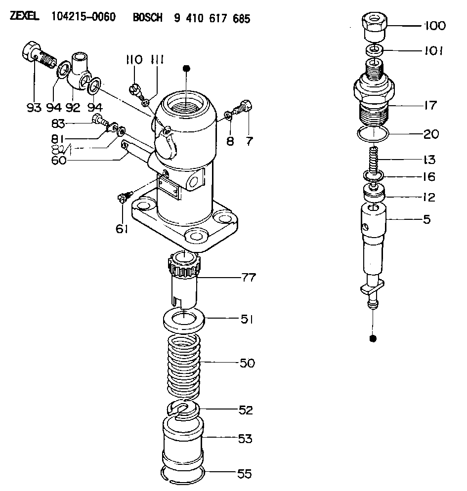
| 5. | [1] | 141171-0520 | PLUNGER-AND-BARREL ASSY |
| 7. | [1] | 141106-8300 | CAPSULE |
| 8. | [1] | 029331-2130 | GASKET |
| 12. | [1] | 141140-8220 | DELIVERY-VALVE ASSEMBLY |
| 13. | [1] | 141112-2000 | COMPRESSION SPRING |
| 16. | [1] | 141115-4600 | GASKET |
| 17. | [1] | 141126-2420 | FITTING |
| 20. | [1] | 029635-0020 | O-RING |
| 50. | [1] | 141215-2601 | COMPRESSION SPRING |
| 51. | [1] | 141216-1800 | SLOTTED WASHER |
| 52. | [1] | 141217-3000 | SLOTTED WASHER |
| 53. | [1] | 141218-5020 | GUIDE |
| 55. | [1] | 141220-1200 | LOCKING WASHER |
| 60. | [1] | 141244-1600 | CONTROL RACK |
| 61. | [1] | 141226-3200 | BLEEDER SCREW |
| 77. | [1] | 141241-2700 | CONTROL SLEEVE |
| 81. | [1] | 141245-2000 | POINTER |
| 82/1. | [0] | 023500-6210 | PLAIN WASHER D11&6.4T1.5 |
| 82/1. | [0] | 029300-6010 | PLAIN WASHER D11&6.4T0.8 |
| 82/1. | [0] | 029300-6020 | PLAIN WASHER D11&6.4T0.35 |
| 83. | [1] | 020006-1440 | BLEEDER SCREW M6P1L14 |
| 92. | [1] | 029702-6060 | INLET UNION |
| 93. | [1] | 029732-6010 | EYE BOLT |
| 94. | [2] | 026526-3440 | GASKET |
| 94. | [2] | 026526-3440 | GASKET |
| 100. | [1] | 029762-6130 | UNION NUT |
| 101. | [1] | 029351-7010 | PLAIN WASHER |
| 110. | [1] | 141420-1600 | BLEEDER SCREW |
| 111. | [1] | 026506-1040 | GASKET D9.9&6.2T1 |
Cross reference number
Zexel num
Bosch num
Firm num
Name
Information:
1. Using tool (A), remove oil filter assembly (1). 2. Remove two bolts (4) and the washers.3. Remove four bolts (3) and the washers.4. Remove six bolts (2) and the washers. Remove the oil filter base assembly, gaskets and O-ring seals. The following steps are for the installation of the oil filter base assembly and the oil filter.5. Check the condition of the O-ring seals and gaskets used for installation of the oil filter base assembly. If any of the seals or gaskets are worn or damaged, use new parts for replacement. Position all gaskets, and install all bolts finger tight before tightening them to the standard torque value.6. Install the O-ring seals in the oil filter base assembly. Put all gaskets and the oil filter base assembly in position on the cylinder block. Install six bolts (2) and the washers that hold it.7. Install four bolts (3) and the washers.8. Position the gasket. Install two bolts (4) and the washers. Tighten all the bolts to standard torque value.9. Install oil filter assembly (1). Follow the instructions with the oil filter assembly for correct installation.Disassemble & Assemble Oil Filter Base Assembly
Start By:a. remove oil filter and oil filter base assembly 1. Remove three O-ring seals (1) from the oil filter base.2. Remove relief valve assembly (2) as follows: a. Slowly loosen bolt (6) to release compression on spring (4).b. Remove bolt (6), relief valve spring seat (5), spring (4) and retainer (3) from the oil filter base. Remove spacer (7) from bolt (6). 3. Remove oil filter bypass valve (8), oil cooler base valve (9) and oil filter bypass valve (10) from the oil filter base as follows: a. Remove oil filter bypass valve (8). Remove plug (11), spring (13) and plunger (14) from the oil filter base. Remove O-ring seal (12) from plug (11). b. Remove oil cooler base valve (9) from the oil filter base. Remove the two bolts and washers that hold oil cooler base valve (9) in position. Remove oil cooler base valve (9). Remove the O-ring seal from the oil filter base. c. Remove oil filter bypass valve (10) from the oil filter base. Slowly remove the two bolts and washers that hold cover (15) in place to release the spring compression. Remove cover (15) and the O-ring seal from the oil filter base. Remove spring assembly (16) and bypass valve (17) from the oil filter base.4. If necessary, remove the stud that holds the oil filter to the oil filter base. The following steps are for the assembly of the oil filter base assembly.5. Be sure all parts of the oil filter base assembly are thoroughly clean prior to assembly. Check the condition of all O-ring seals prior to assembly of the oil filter base assembly. If any of the seals are worn or damaged, use new parts for replacement.6. If the stud which holds the oil filter to the oil filter base was removed, reinstall it. Tighten the stud to
Start By:a. remove oil filter and oil filter base assembly 1. Remove three O-ring seals (1) from the oil filter base.2. Remove relief valve assembly (2) as follows: a. Slowly loosen bolt (6) to release compression on spring (4).b. Remove bolt (6), relief valve spring seat (5), spring (4) and retainer (3) from the oil filter base. Remove spacer (7) from bolt (6). 3. Remove oil filter bypass valve (8), oil cooler base valve (9) and oil filter bypass valve (10) from the oil filter base as follows: a. Remove oil filter bypass valve (8). Remove plug (11), spring (13) and plunger (14) from the oil filter base. Remove O-ring seal (12) from plug (11). b. Remove oil cooler base valve (9) from the oil filter base. Remove the two bolts and washers that hold oil cooler base valve (9) in position. Remove oil cooler base valve (9). Remove the O-ring seal from the oil filter base. c. Remove oil filter bypass valve (10) from the oil filter base. Slowly remove the two bolts and washers that hold cover (15) in place to release the spring compression. Remove cover (15) and the O-ring seal from the oil filter base. Remove spring assembly (16) and bypass valve (17) from the oil filter base.4. If necessary, remove the stud that holds the oil filter to the oil filter base. The following steps are for the assembly of the oil filter base assembly.5. Be sure all parts of the oil filter base assembly are thoroughly clean prior to assembly. Check the condition of all O-ring seals prior to assembly of the oil filter base assembly. If any of the seals are worn or damaged, use new parts for replacement.6. If the stud which holds the oil filter to the oil filter base was removed, reinstall it. Tighten the stud to