Information ring sub-assy, rol
RING SUB-ASSY, ROL
AA
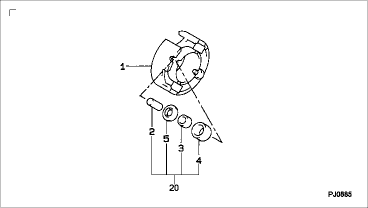
- IN THE ROLLER PIN KIT,NO.2,3,4,5 EACH INCLUDE 4 PIECES.
RING SUB-ASSY, ROL
EB
- IN THE ROLLER PIN KIT,NO.2,3,4,5 EACH INCLUDE 4 PIECES.
RING SUB-ASSY, ROL
GA
- IN THE ROLLER PIN KIT,NO.2,3,4,5 EACH INCLUDE 4 PIECES.
RING SUB-ASSY, ROL
LA
- IN THE ROLLER PIN KIT,NO.2,3,4,5 EACH INCLUDE 4 PIECES.
RING SUB-ASSY, ROL
ZA
- IN THE ROLLER PIN KIT,NO.2,3,4,5 EACH INCLUDE 4 PIECES.
Rating:
Scheme ###:
| 000. | [01] | 09618-00150 | RING SUB-ASSY, ROL | 22108-56330-000 |
| 000. | [01] | 09618-00150 | RING SUB-ASSY, ROL | |
| 000. | [01] | 09618-00150 | RING SUB-ASSY, ROL | 22108-96300 |
| 000. | [01] | 09618-00150 | RING SUB-ASSY, ROL | 22108-78300-71 |
| 000. | [01] | 09618-00150 | RING SUB-ASSY, ROL | |
| 001. | [01] | 09618-10140 | RING, ROLLER | |
| 001. | [01] | 09618-10140 | RING, ROLLER | |
| 001. | [01] | 09618-10140 | RING, ROLLER | |
| 001. | [01] | 09618-10140 | RING, ROLLER | |
| 001. | [01] | 09618-10140 | RING, ROLLER | |
| 002. | [04] | 09618-40020 | PIN, ROLLER | |
| 002. | [04] | 09618-40020 | PIN, ROLLER | |
| 002. | [04] | 09618-40020 | PIN, ROLLER | |
| 002. | [04] | 09618-40020 | PIN, ROLLER | |
| 002. | [04] | 09618-40020 | PIN, ROLLER | |
| 003. | [04] | 09618-50020 | BUSH, ROLLER | |
| 003. | [04] | 09618-50020 | BUSH, ROLLER | |
| 003. | [04] | 09618-50020 | BUSH, ROLLER | |
| 003. | [04] | 09618-50020 | BUSH, ROLLER | |
| 003. | [04] | 09618-50020 | BUSH, ROLLER | |
| 004. | [04] | 09618-70030 | ROLLER | |
| 004. | [04] | 09618-70050 | ROLLER | |
| 004. | [04] | 09618-70050 | ROLLER | |
| 004. | [04] | 09618-70030 | ROLLER | |
| 004. | [04] | 09618-70050 | ROLLER | |
| 004. | [04] | 09618-70030 | ROLLER | |
| 004. | [04] | 09618-70050 | ROLLER | |
| 004. | [04] | 09618-70030 | ROLLER | |
| 004. | [04] | 09618-70050 | ROLLER | |
| 004. | [04] | 09618-70030 | ROLLER | |
| 005. | [04] | 09618-90020 | PLATE, ROLLER | |
| 005. | [04] | 09618-90020 | PLATE, ROLLER | |
| 005. | [04] | 09618-90020 | PLATE, ROLLER | |
| 005. | [04] | 09618-90020 | PLATE, ROLLER | |
| 005. | [04] | 09618-90020 | PLATE, ROLLER | |
| 020. | [01] | 09601-00930 | OVER-HAUL KIT, DIS | |
| 020. | [01] | 09601-00930 | OVER-HAUL KIT, DIS | |
| 020. | [01] | 09601-00930 | OVER-HAUL KIT, DIS | |
| 020. | [01] | 09601-00930 | OVER-HAUL KIT, DIS | |
| 020. | [01] | 09601-00930 | OVER-HAUL KIT, DIS |
Include in #3:
Cross reference number
| Part num | Firm num | Firm | Name |
| 09618-00150 | RING SUB-ASSY, ROL | ||
| 22108-96300 | TOYOTA | RING SUB-ASSY, ROL | |
| 22108-78300-71 | TICO | RING SUB-ASSY, ROL | |
| 22108-56350-000 | DAIHATSU | RING SUB-ASSY, ROL | |
| 22108-56330-000 | DAIHATSU | RING SUB-ASSY, ROL |
Information:
1. Disconnect plug P14 from receptacle J14. The locking ring helps identify P14 from J14. Check the connections for damaged wires or pins and corrosion. Also check that the pins are at the proper height in the connector. Check that the wires and pins are tight in the connectors by pulling (slightly) on each wire of each connector (including the breakout "T").2. Install 8T8694 Adapter (five pin breakout "T") between J14 and P14. Twist the locking rings to secure the connections.3. Connect the voltmeter as shown. Check for the appropriate voltages between the lettered "T" pins as explained in Steps 4 through 7.4. Pin A (+) to pin B (ground) system voltage should be approximately 12 volts DC with key on (no accessories). Minimum voltage is 11.0 volts DC. Diagnosis - Using the truck wiring schematic, check wires A and B and connections from J14 through the truck wiring harness back to the battery for proper voltage.5. If the voltage check between pins A and B is less than 11.0 volts with the key on, check the voltage drop from pin B to the negative battery post while cranking. For this test, the common lead (black) should be connected to the negative battery post first. Then place the positive (red) lead into pin B. (Pin B is chassis ground.) Voltage should be less than .5 volts DC when cranking. Diagnosis - If the voltage drop is greater than .5 volts DC, check wire B and connections (including the battery post connections) from J14 to battery negative. Follow the truck wiring schematic to trace the electrical path from J14 Pin B to chassis ground.6. Check buffer operation. Step 6 checks the proper functioning of the truck wiring, vehicle speed sensor and vehicle speed buffer. If proper vehicle speed is present on the appropriate status screens of the 3406B (PEEC III) (7X6400) DDT or the (8T8697) ECAP service tools during road test then Step 6 is not necessary.A. Check wires and connectors for damage or corrosion from the magnetic pickup to vehicle speed buffer.B. Remove magnetic pickup (vehicle speed sensor) from transmission. If pickup has collected significant metal debris, wipe it clean. Check the magnetic pickup per the manufactures specifications. Install a properly functioning magnetic pickup to the proper depth and reconnect to the vehicle speed buffer. Check for proper system operation. The problem may reappear if transmission fluid is contaminated. Change transmission fluid if necessary.C.1. Disconnect the magnetic pickup from the vehicle speed buffer.C.2. Jumper the white vehicle speed buffer wire (input from magnetic pickup) to J14 Pin A (+ battery) at the breakout "T".* Voltage from pins D to B of breakout "T" is less than 1.0 volt DC with key on and engine off.* Voltage from pins C to B is -8.0 to -10.0 volts DC with key on.* Voltage from pins E to B is +8.0 to +10.0 volts DC with key on.C.3. Move the white input wire (jumper) to J14 Pin B (- battery) and