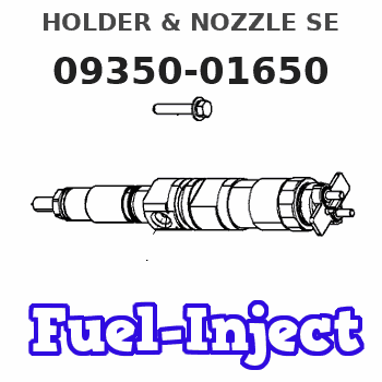
Information holder & nozzle se
Rating:
Components :
| 001. | HOLDER & NOZZLE SE | 09350-01650 |
Scheme ###:
| 000. | [01] | 09350-01650 | HOLDER & NOZZLE SE | MM402970 |
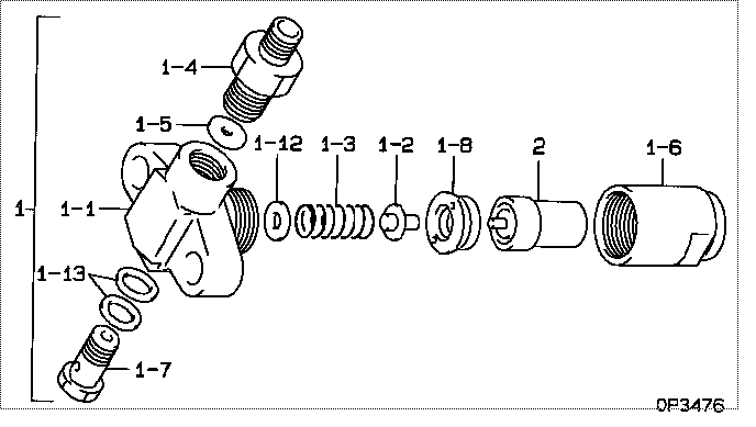
| 001. | [01] | 09310-01650 | HOLDER ASSY, NOZZL | |
| 001-001. | [01] | 09311-11650 | BODY | MM500892 |
| 001-002. | [01] | 09312-10030 | PIN, NOZZLE HOLDER | MM500135 |
| 001-003. | [01] | 09312-70020 | SPRING, NOZZLE HOL | ME022313 |
| 001-004. | [01] | 09315-10280 | CONNECTOR, NOZZLE | ME728005 |
| 001-005. | [01] | 09315-80010 | GASKET, INLET CONN | MM500889 |
| 001-006. | [01] | 09316-40242 | NUT, NOZZLE RETAIN | MM500890 |
| 001-007. | [01] | 09316-60010 | SCREW, HOLLOW | P820-8362 |
| 001-008. | [01] | 09317-40011 | DISTANCE PIECE | ME703620 |
| 001-012. | [1C] | 09317-50120 | WASHER | MM500776 |
| 001-012. | [1C] | 09317-50130 | WASHER | MM500777 |
| 001-012. | [1C] | 09317-50140 | WASHER | MM500778 |
| 001-012. | [1C] | 09317-50150 | WASHER | MM500779 |
| 001-012. | [1C] | 09317-50160 | WASHER | MM500780 |
| 001-012. | [1C] | 09317-50170 | WASHER | MM500781 |
| 001-012. | [1C] | 09317-50180 | WASHER | MM500782 |
| 001-012. | [1C] | 09317-50190 | WASHER | MM500783 |
| 001-012. | [1C] | 09317-50200 | WASHER | MM500784 |
| 001-012. | [1C] | 09317-50110 | WASHER | MM500775 |
| 001-012. | [1C] | 09317-50100 | WASHER | MM500774 |
| 001-012. | [1C] | 09317-50010 | WASHER | MM500765 |
| 001-012. | [1C] | 09317-50020 | WASHER | MM500766 |
| 001-012. | [1C] | 09317-50030 | WASHER | MM500767 |
| 001-012. | [1C] | 09317-50040 | WASHER | MM500768 |
| 001-012. | [1C] | 09317-50050 | WASHER | MM500769 |
| 001-012. | [1C] | 09317-50060 | WASHER | MM500770 |
| 001-012. | [1C] | 09317-50070 | WASHER | MM500771 |
| 001-012. | [1C] | 09317-50080 | WASHER | MM500772 |
| 001-012. | [1C] | 09317-50090 | WASHER | MM500773 |
| 001-013. | [02] | 94901-81020 | WASHER, COPPER PLA | ME022309 |
| 002. | [01] | 09340-00010 | NOZZLE ASSY | ME020996 |
Include in #3:
09350-01650
as HOLDER & NOZZLE SE
Cross reference number
| Part num | Firm num | Firm | Name |
| 09350-01650 | MM402970 | HOLDER & NOZZLE SE | |
| MM402970 | MITSUBISHI | HOLDER & NOZZLE SE |
Information:
Turn the engine to top dead center, (TDC), compression stroke for the No. 1 piston.1. Remove bolts (1), cover (2) and the gasket.
Camshaft Timing2. Remove two bolts (3) and carefully remove camshaft retainer (4) with the camshaft from the cylinder block. If necessary, remove camshaft gear (5) from the camshaft with a press. The following steps are for the installation of the camshaft.3. If camshaft gear was removed, use the following procedure to reinstall. Heat camshaft gear (5) to a maximum temperature of 315° C (600° F).4. Align the key in the camshaft with the groove (keyway) in gear (5). Install gear (5) on the camshaft.5. Use 8T2998 Camshaft Lubricant on the lobes and journals of the camshaft.6. Carefully, install the camshaft in the cylinder block, positioning retainer (4) and install bolts (3). When installing camshaft, be sure number one cylinder is at top dead center, (TDC), of compression stroke. Camshaft timing is very important. Cam gear timing mark must line up with idler gear timing mark, as illustrated, when the crankshaft idler gear timing is also aligned. For more information about timing of the engine, refer to Specifications section of this service manual.
Do not over torque bolts (1), damage to the gasket could occur.
7. Position gasket, cover (2) and install bolts (1).End By:a. install front pulley and damperb. install governorc. install side cover and cam followers (if previously removed)d. install push rodse. install rocker arm assemblies