Information valve body
BOSCH
9 441 610 101
9441610101
ZEXEL
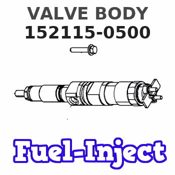
152115-0500
1521150500
ISUZU
1157550020
1157550020
Rating:
Compare Prices: .
As an associate, we earn commssions on qualifying purchases through the links below

$15.95
10 Mar 2023
US: NKR Diesel Parts
Valve Compatible With/Replacement For Chevrolet W3500 Tiltmaster 2004-2006, W4500 Tiltmaster 2004-2007, Isuzu NPR 2004-2006, NPR-HD 2004-2007, NQR 2004-2007 4HE1, 4HK1 Turbocharged 1157550020
NKR DIESEL PARTS
NKR DIESEL PARTS

$6.99
24 Oct 2021
US: Boursin Auto Parts
Feed pump Valve Repair kit For Zexel Bosch Feed Pump Mitsubishi Fuso Canter Forklift Isuzu Npr Nqr Nkr Nrr FTR FSR FRR FVR Hino UD Komatsu Dozer Caterpillar CAT Excavator Diesel
Boursin Used for isuzu mitsubishi fuso ud hino komatsu pc200 hitachi ex200 forklift excavator diesel engine || Engine: 4BE1 4HG1 4HF1 6BD1 6BG1 6HH1 6HE1 6HK1 S4Q S4S S4E S6S 4D30 4D31 4D32 4D33 4D34 4D35 4D36 6D14 6D15 6D16 6D17 6D22 6D102 6D95 6D125 || Fit For Zexel Bosch Feed Pump
Boursin Used for isuzu mitsubishi fuso ud hino komatsu pc200 hitachi ex200 forklift excavator diesel engine || Engine: 4BE1 4HG1 4HF1 6BD1 6BG1 6HH1 6HE1 6HK1 S4Q S4S S4E S6S 4D30 4D31 4D32 4D33 4D34 4D35 4D36 6D14 6D15 6D16 6D17 6D22 6D102 6D95 6D125 || Fit For Zexel Bosch Feed Pump

$15.60
23 Oct 2021
US: # 1 Quality Parts
VALVE FOR ALLIS-CHALMERS: 1-15755-002-0
Parts Express ALLIS-CHALMERS || All Brand new & rebuilt items comes with 1 year warranty. || VALVE. Category: ALLIS-CHALMERS FORKLIFT PARTS. This part can also be found under the following part numbers: AC1-15755-002-0 1-15755-002-0 ALLIS CHALMERS/TUSK AC 1-15755-002-0 ALLIS CHALMERS/TUSK1-15755-002-0 AC1157550020 AC 1157550020 Â 1-15755-002-0 ALLIS CHALMERS/TUSK 1157550020 ALLIS CHALMERS/TUSK1157550020 Â 1157550020. All Brand new & rebuilt items comes with 1 year warranty.
Parts Express ALLIS-CHALMERS || All Brand new & rebuilt items comes with 1 year warranty. || VALVE. Category: ALLIS-CHALMERS FORKLIFT PARTS. This part can also be found under the following part numbers: AC1-15755-002-0 1-15755-002-0 ALLIS CHALMERS/TUSK AC 1-15755-002-0 ALLIS CHALMERS/TUSK1-15755-002-0 AC1157550020 AC 1157550020 Â 1-15755-002-0 ALLIS CHALMERS/TUSK 1157550020 ALLIS CHALMERS/TUSK1157550020 Â 1157550020. All Brand new & rebuilt items comes with 1 year warranty.
Include in ###:
Cross reference number
Zexel num
Bosch num
Firm num
Name
152115-0500
9 441 610 101
1157550020 ISUZU
VALVE BODY
C 14GD VALVE F/P
C 14GD VALVE F/P
152115-0500
9 441 610 101
225631150A HINO
VALVE BODY
C 14GD VALVE F/P
C 14GD VALVE F/P
152115-0500
9 441 610 101
S225631150 HINO
VALVE BODY
A C 14GD VALVE F/P
A C 14GD VALVE F/P
152115-0500
9 441 610 101
ME726483 MITSUBISHI
VALVE BODY
C 14GD VALVE F/P
C 14GD VALVE F/P
152115-0500
9 441 610 101
1706589TA0 NISSAN
VALVE BODY
C 14GD VALVE F/P
C 14GD VALVE F/P
152115-0500
9 441 610 101
16647Z9002 NISSAN-DIESEL
VALVE BODY
C 14GD VALVE F/P
C 14GD VALVE F/P
152115-0500
9 441 610 101
12666452210 YANMAR
VALVE BODY
C 14GD VALVE F/P
C 14GD VALVE F/P
Information:
Illustration 1 g00564355
7W-2743 Electronic Speed Switch (ESS)
(1) Push button for Overspeed Verification
(2) Reset button
(3) Overspeed indicator lamp
(4) Seal screw plug for adjusting the engine overspeed
(5) Seal screw plug for adjusting the crank terminate speed
(6) Seal screw plug for adjusting the oil step pressure speed setting The oil step speed calibration increases the oil step speed setting or the oil step speed calibration decreases the oil step speed setting. Refer to the Speed Specification Chart in order to find the oil step speed that is equal to the engine rpm when the engine is running.
Remove the lockwire and the seal from seal screw plug (6). Remove seal screw plug (6) from the access hole for the oil step speed adjusting screw.
Use a small screwdriver to lightly turn the oil step speed adjusting screw in the direction of the "MAX" arrow or the clockwise direction. Turn the screw twenty times. The oil step speed adjusting screw will vary the setting of a potentiometer that is inside of the ESS. The oil step speed adjusting screw will not cause damage to the potentiometer. Also, the screw can not be removed if the screw is turned in the wrong direction.
Connect a voltmeter with the positive lead at terminal (ESS-13) and the negative lead at (ESS-5). Use a 6V-7070 Digital Multimeter or a voltmeter with the same accuracy. Measure the voltage.
For a specific engine rating, find the engine rpm in the column for the oil step speed setting in the Speed Specification Chart. Run the engine at the rpm that is specified in the table.
While the engine is running, look into the hole for the adjustment of the oil step speed. A red indicator lamp should be lighted. A positive voltage should be observed on the multimeter 9 seconds after the indicator lamp is lighted. Turn the oil step speed adjusting screw clockwise until the indicator lamp turns off. The oil step speed setting is above the present rpm of the engine. Slowly turn the oil step speed adjusting screw counterclockwise until the indicator lamp is lighted. After a 9 second delay, a positive voltage should be observed on the multimeter. This position is the correct setting for the oil step speed.
Install seal screw plug (6) in the access hole for the oil step speed adjusting screw. Tighten the screw to a torque of 0.20 0.03 N m (1.8 .3 lb in). Install the lockwire and the seal if the overspeed calibration and the crank terminate speed calibration are also complete.
Have questions with 152115-0500?
Group cross 152115-0500 ZEXEL
Isuzu
152115-0500
9 441 610 101
1157550020
VALVE BODY
Hino
152115-0500
9 441 610 101
225631150A
VALVE BODY
152115-0500
9 441 610 101
S225631150
VALVE BODY
Mitsubishi
152115-0500
9 441 610 101
ME726483
VALVE BODY
Nissan
152115-0500
9 441 610 101
1706589TA0
VALVE BODY
Nissan-Diesel
152115-0500
9 441 610 101
16647Z9002
VALVE BODY
Yanmar
152115-0500
9 441 610 101
12666452210
VALVE BODY