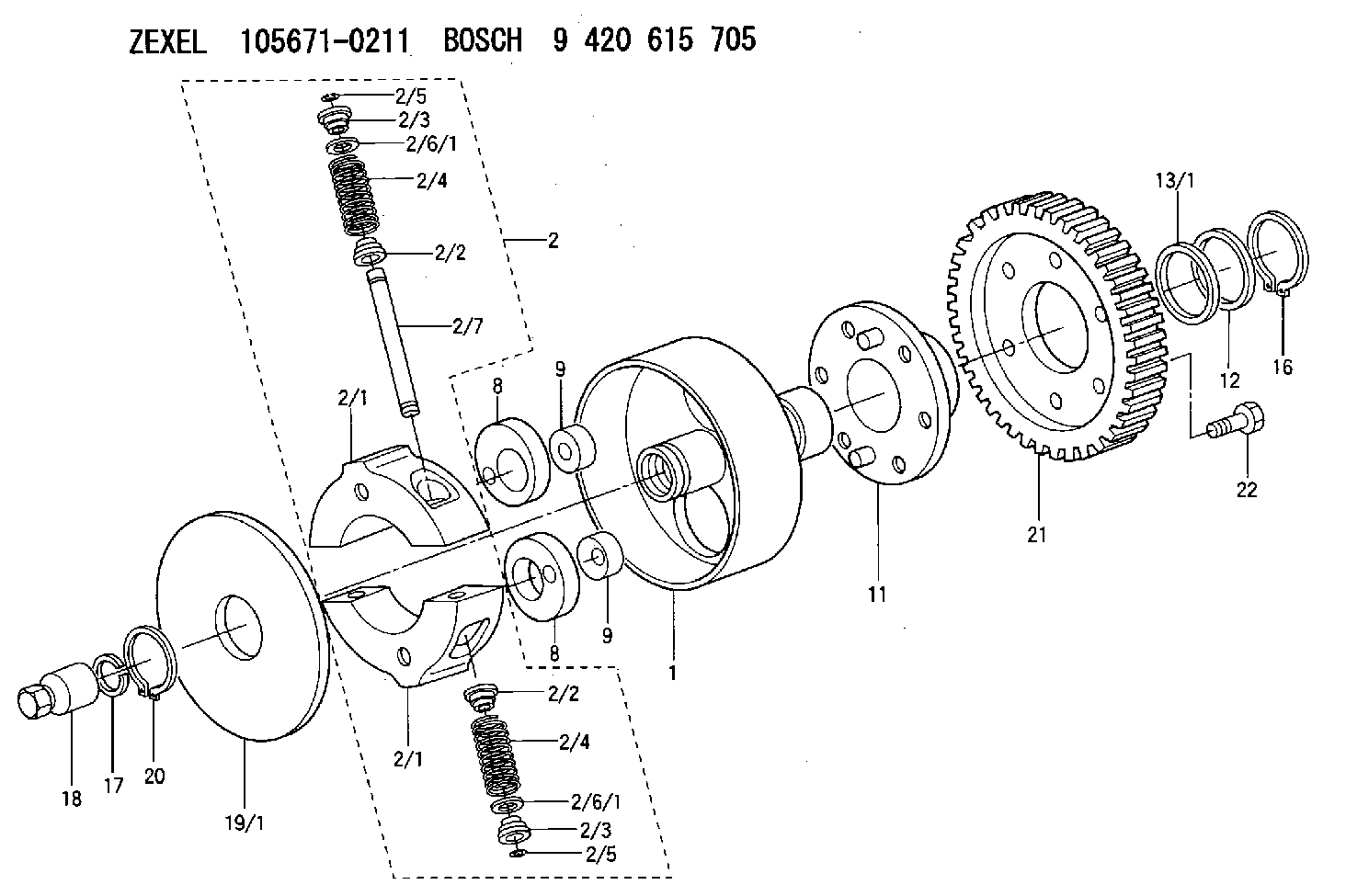
Information toothed gear
BOSCH
9 423 612 469
9423612469
ZEXEL
156221-2100
1562212100
ISUZU
1125240520
1125240520

Rating:
Include in ###:
Cross reference number
Zexel num
Bosch num
Firm num
Name
156221-2100
9 423 612 469
1125240520 ISUZU
TOOTHED GEAR
B 14GQ GEAR TIMER
B 14GQ GEAR TIMER
Information:
Test Procedure
System Operation
The SLC 5/04 diagnostic indicators are located on the front of the following components: Power Supply, CPU and I/O Modules.The diagnostic indicators help trace the source of the fault. Faults can be found in the following components: Input devices, Output devices, Wiring and The controller.The green "RUN" LED is illuminated. The processor is in the "RUN" mode.The red "FLT" LED is flashing during operation. The processor detects a major fault. The fault is in the processor expansion chassis or the fault is in the memory.The amber "FORCE" LED is illuminated. The forces are enabled.The amber "FORCE" LED is not illuminated. No forces are present or no forces are enabled.
Illustration 1 g00563544
Diagram of the LED indicators
Illustration 2 g00562937
Functional Test
Check the electrical connectors and check the wiring.
Bodily contact with electrical potential can cause bodily injury or death.To avoid the possibility of injury or death, ensure that the main power supply has been disconnected before performing any maintenance or removing any modules.
Disconnect the power supply.
Check the electrical connectors and check the wiring for damage or bad connections.
Verify that all modules are properly seated.
Verify the status of the LED on the SLC 5/04.The results of the preceding procedure are in the following list:
All of the components are fully installed. All of the components are free of corrosion. All of the components are free of damage. All of the modules are properly seated. Proceed to 2.
The components are not fully installed. The components are not free of corrosion. The components are damaged. All of the modules are not properly seated. Repair the component. Verify that the repair resolves the problem. STOP.
Clear the fault.
Place the switch in the PROG position.
Place the switch in the RUN position.The results of the preceding procedure are in the following list:
No errors are displayed on the LED indicators. Stop.
Errors are displayed on the LED indicators. Proceed to 3.
Cycle the power.
Secure power to the PLC.
Energize the PLC.The results of the preceding procedure are in the following list:
No errors are displayed on the LED indicators. Stop.
Errors are displayed on the LED indicators. Refer to Maintenance Procedure, "Processor - Replace".
Have questions with 156221-2100?
Group cross 156221-2100 ZEXEL
Isuzu
156221-2100
9 423 612 469
1125240520
TOOTHED GEAR