Information terminal
BOSCH
9 443 612 237
9443612237
ZEXEL
158906-0800
1589060800
Rating:
Include in ###:
Cross reference number
Zexel num
Bosch num
Firm num
Name
Information:
3. Inspection
Inspection points4. Assembly
Assembly sequenceFollow the reverse of disassembly and use the procedure that follows. Assembly procedure (1) Barrel installationPut each barrel in position in the housing with its slot in alignment with the dowel of the housing and put it straight down into the bore. If the slot in the barrel is not aligned with the dowel of the housing, the O-ring will not seat correctly (still visible) after the delivery valve holder has been installed.
Installing barrels(2) Delivery valve installationInstall the delivery valve, gasket, spring and O-ring on the barrel and tighten the delivery valve holder finger tight. Do this step for remainder of the delivery valves.
a) Any time the injection pump is disassembled, a new O-ring must be installed.b) Make sure the threads of the delivery valve holder do not cause damage to the O-rings.
Installing delivery valves(3) Control sleeve installation (a) Install each control sleeve with the center tooth in alignment with the line mark of the control rack.
Installing control sleeves(b) Put the plungers in position in the barrels.
Make sure the notch in the plunger is toward the adjusting plate.
Installing plungers(4) Tappet installationMove the control rack back and forth while pushing down on each tappet to align the slot in the tappet with the hole in the housing for the tappet guide pin. Install the lock plates and tappet guide pins in position.
Any time the injection pump is disassembled, new lock plates must be used.
Installing tappets(5) Delivery valve holder installation Put the delivery valve holders in position and tighten them to the specified torque.
Do not over tighten the delivery valve holders. This can put end force on the barrels, resulting in a failure of the plungers to move freely. If the holders are not tightened to the specified torque, engine oil would leak in the injection pump.
Tightening delivery valve holders(6) Inspection after assembly (a) After the injection pump has been assembled, check to see if the control rack moves freely without any binding or catching.(b) If the control rack fails to move freely, the possible causes are:1) Pumping element(s) sticking2) Foreign particles lodged between control rack and sleeves3) Over-tightening of delivery valve holder(s)Disassemble and check the injection pump to locate the cause of the trouble. (c) After the injection pump has been finally assembled, check the injection timing.
Checking control rack movementGOVERNOR
1. Disassembly and inspection
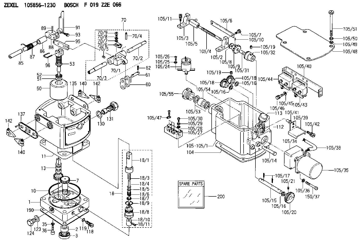
Disassembly sequence and inspection points1 Tie rod spring2 Tie rod3 Speed control lever4 Spring pin5 Grooved pin6 Governor shaft (Remove 7 thru 11 as an assembly.)7 Governor lever8 Start spring9 Tension lever10 Governor spring11 Governor spring lever12 Governor case2. Assembly (1) Install the levers in position.
Installing governor levers(2) Put O-ring on the governor shaft. (3) Put the governor shaft in position in the governor case and put the levers on the governor shaft. (4) Install the grooved pin and spring pin in position with a hammer.(5) Install the tie rod and tie rod spring in position.
Assembling governor3. Torque spring set installation The torque spring set is to be installed and adjusted after an
Inspection points4. Assembly
Assembly sequenceFollow the reverse of disassembly and use the procedure that follows. Assembly procedure (1) Barrel installationPut each barrel in position in the housing with its slot in alignment with the dowel of the housing and put it straight down into the bore. If the slot in the barrel is not aligned with the dowel of the housing, the O-ring will not seat correctly (still visible) after the delivery valve holder has been installed.
Installing barrels(2) Delivery valve installationInstall the delivery valve, gasket, spring and O-ring on the barrel and tighten the delivery valve holder finger tight. Do this step for remainder of the delivery valves.
a) Any time the injection pump is disassembled, a new O-ring must be installed.b) Make sure the threads of the delivery valve holder do not cause damage to the O-rings.
Installing delivery valves(3) Control sleeve installation (a) Install each control sleeve with the center tooth in alignment with the line mark of the control rack.
Installing control sleeves(b) Put the plungers in position in the barrels.
Make sure the notch in the plunger is toward the adjusting plate.
Installing plungers(4) Tappet installationMove the control rack back and forth while pushing down on each tappet to align the slot in the tappet with the hole in the housing for the tappet guide pin. Install the lock plates and tappet guide pins in position.
Any time the injection pump is disassembled, new lock plates must be used.
Installing tappets(5) Delivery valve holder installation Put the delivery valve holders in position and tighten them to the specified torque.
Do not over tighten the delivery valve holders. This can put end force on the barrels, resulting in a failure of the plungers to move freely. If the holders are not tightened to the specified torque, engine oil would leak in the injection pump.
Tightening delivery valve holders(6) Inspection after assembly (a) After the injection pump has been assembled, check to see if the control rack moves freely without any binding or catching.(b) If the control rack fails to move freely, the possible causes are:1) Pumping element(s) sticking2) Foreign particles lodged between control rack and sleeves3) Over-tightening of delivery valve holder(s)Disassemble and check the injection pump to locate the cause of the trouble. (c) After the injection pump has been finally assembled, check the injection timing.
Checking control rack movementGOVERNOR
1. Disassembly and inspection
Disassembly sequence and inspection points1 Tie rod spring2 Tie rod3 Speed control lever4 Spring pin5 Grooved pin6 Governor shaft (Remove 7 thru 11 as an assembly.)7 Governor lever8 Start spring9 Tension lever10 Governor spring11 Governor spring lever12 Governor case2. Assembly (1) Install the levers in position.
Installing governor levers(2) Put O-ring on the governor shaft. (3) Put the governor shaft in position in the governor case and put the levers on the governor shaft. (4) Install the grooved pin and spring pin in position with a hammer.(5) Install the tie rod and tie rod spring in position.
Assembling governor3. Torque spring set installation The torque spring set is to be installed and adjusted after an