Information supply pump
BOSCH
9 440 610 395
9440610395
ZEXEL
105237-6100
1052376100
Rating:
Scheme ###:
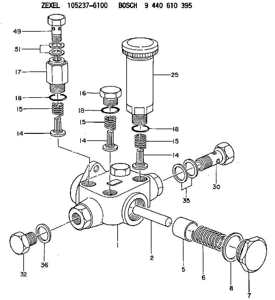
| 1. | [1] | 152060-0020 | PUMP HOUSING |
| 2. | [1] | 152030-0100 | STOP PIN |
| 5. | [1] | 152100-2301 | PUMP PLUNGER |
| 6. | [1] | 152102-0400 | COMPRESSION SPRING |
| 7. | [1] | 152105-1500 | CAPSULE |
| 8. | [1] | 139526-0000 | GASKET |
| 14. | [4] | 152115-0500 | VALVE BODY |
| 14. | [4] | 152115-0500 | VALVE BODY |
| 14. | [4] | 152115-0500 | VALVE BODY |
| 15. | [4] | 152116-0200 | COILED SPRING |
| 15. | [4] | 152116-0200 | COILED SPRING |
| 15. | [4] | 152116-0200 | COILED SPRING |
| 16. | [2] | 152117-0620 | CAPSULE |
| 17. | [1] | 152118-1700 | ADAPTOR |
| 18. | [4] | 029631-6060 | O-RING |
| 18. | [4] | 029631-6060 | O-RING |
| 18. | [4] | 029631-6060 | O-RING |
| 25. | [1] | 152200-6720 | HAND PRIMER |
| 30. | [1] | 152300-7120 | EYE BOLT |
| 32. | [1] | 029111-4050 | CAPSULE |
| 35. | [2] | 029341-4130 | GASKET D20&13.8T2* |
| 36. | [1] | 029341-4130 | GASKET D20&13.8T2* |
| 49. | [1] | 029731-4680 | EYE BOLT |
| 51. | [2] | 029341-4130 | GASKET D20&13.8T2* |
Include in #1:
108822-2000
as SUPPLY PUMP
Cross reference number
Zexel num
Bosch num
Firm num
Name
105237-6100
9 440 610 395
SUPPLY PUMP
* K 14GC FEED PUMP F/P
* K 14GC FEED PUMP F/P
Information:
Product smu/age whichever comes first Caterpillar Dealer Suggested Customer Suggested
Parts % Labor Hrs% Parts % Labor Hrs% Parts % Labor Hrs%
*******Group 2*******
0-6000 hrs,
0-48 mo 100.0% 100.0% 0.0% 0.0% 0.0% 0.0%
This is a 4.0-hour job for Group 2
PARTS DISPOSITION
Handle the parts in accordance with your Warranty Bulletin on warranty parts handling.
Rework Procedure
1. Park the machine on level ground, lower all implements to the ground, shut off machine, and relieve all hydraulic system pressure.
2. Read and understand this Rework Procedure before starting work.
3. See Image 1.2.1 for the general location of the DEF Module Group and reference views that will be used in future steps.
Image1.2.1
(A) Fuel tank; (B) Diesel Exhaust Fluid (DEF) Module Group
DEF tank cover not shown for clarity
4. Inspect control harness assembly (2) at location (AA) and hose assembly (3) at location (BB) for rubbing and or fouling on the DEF Tank Cover (See Image 1.4.1). If either item is damaged, replace both assembly (2) and (3).
396-3862 Control Harness Assembly (2) is compatible with serial numbers equipped WITHOUT a DEF Quality Sensor (FMC1-00772). 524-5527 Control Harness Assembly (2) is compatible with serial numbers equipped WITH a DEF Quality Sensor (FMC00773-Up).
Hardware (C) holding the DEF Module Group to the fuel tank and clamp (E) holding DEF Fill Hose (D) to the tank will need to be loosened to reposition the DEF Module Group to access control harness assembly (2) and hose assembly (3).
Image1.4.1
5. After control harness assembly (2) and hose assembly (3) have been inspected and found without damage OR replaced, secure both parts using Steps 6 through 9.
6. Secure control harness assembly (2) and hose assembly (3) to left side of DEF Module (F) using tie straps (4). (See Image 1.6.1)
The Fuel tank is not shown for clarity.
Image1.6.1
At location (CC), use tie straps (4) to secure harness bundles (G) to prevent harness from contacting the fuel tank. (See Image 1.7.1)
Image1.7.1
At location (DD), use tie straps (4) to secure control harness assembly (2) and hose assembly (3), and terminating resistor (H) at lower location. (See Image 1.8.1)
Image1.8.1
7. Reposition the DEF Module Group, install 560-4252 Bracket Assembly (1), and reinstall the remaining hardware (C), clamp (E) removed in Step 4. Check to make sure control harness assembly (2) and hose assembly (3) will not contact the DEF Tank Cover. (See Image 1.9.1)
Image1.9.1
8. Secure control harness assembly (2) and hose assembly (3) to top of DEF Module Group using tie straps (4) as shown in Image 1.10.1. Check to make sure control harness assembly (2) and hose assembly (3) will not contact the DEF Tank Cover.
Note: Existing P-clip (J) will need to be flipped from the original position.
Image1.10.1
9. Secure control harness assembly (2) and hose assembly (3) to the rear and right side of Diesel Exhaust Fluid Module using tie straps (4) as shown in Image 1.11.1. Check to make sure control harness assembly (2) and hose assembly (3) will not contact the DEF Tank Cover.
Image1.11.1
Have questions with 105237-6100?
Group cross 105237-6100 ZEXEL
105237-6100
9 440 610 395
SUPPLY PUMP