Information supply pump
BOSCH
9 440 610 953
9440610953
ZEXEL
105237-5750
1052375750
NIIGATA-TEKKOU
75L48110A
75l48110a
Rating:
Scheme ###:
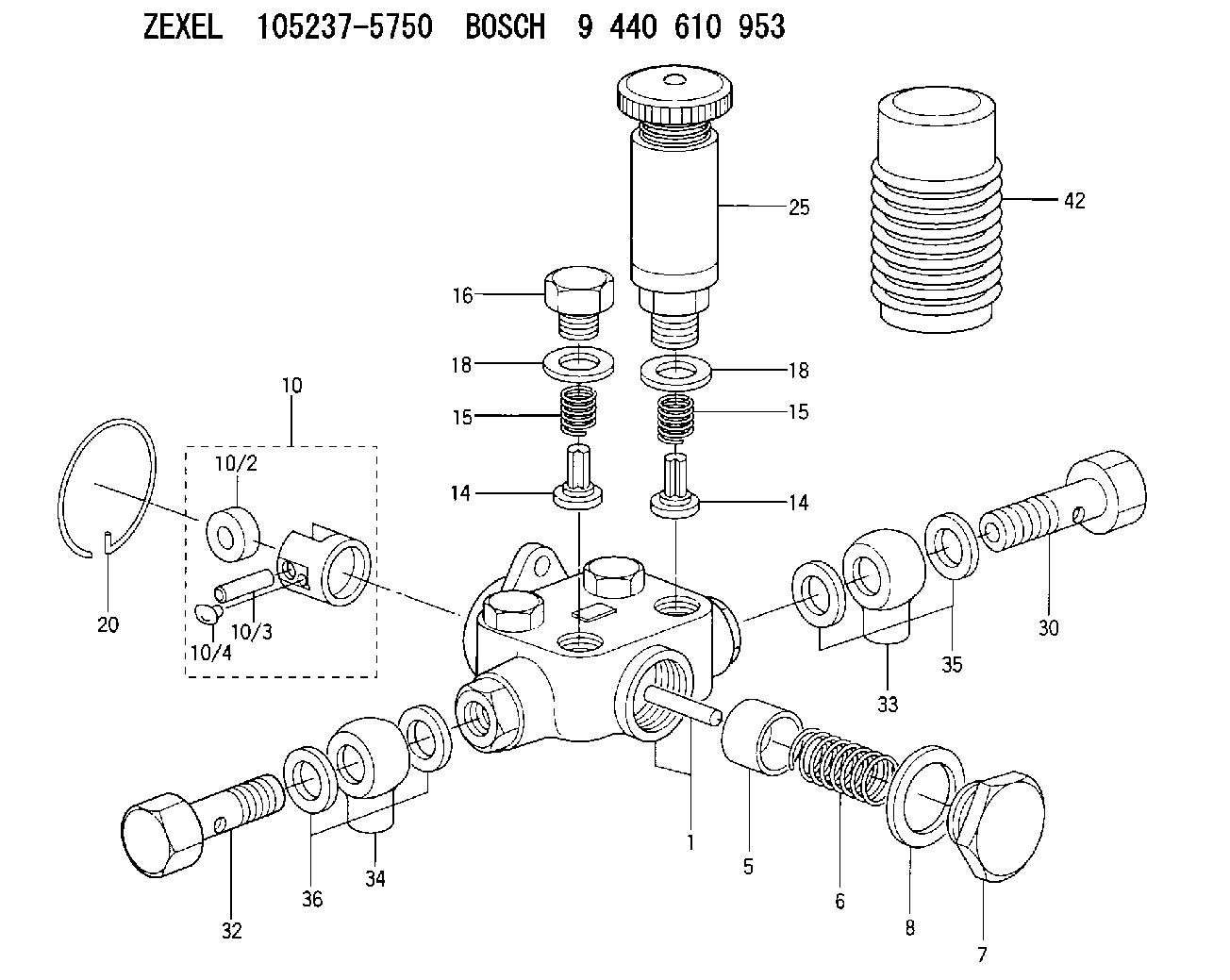
| 1. | [1] | 152050-0820 | PUMP HOUSING |
| 5. | [1] | 152100-1120 | PUMP PLUNGER |
| 6. | [1] | 152102-1300 | COMPRESSION SPRING |
| 7. | [1] | 152105-1500 | CAPSULE |
| 8. | [1] | 029332-6030 | GASKET |
| 10. | [1] | 152111-4420 | TAPPET |
| 10/2. | [1] | 152112-0800 | ROLLER |
| 10/3. | [1] | 152113-1300 | BEARING PIN |
| 10/4. | [2] | 152114-1600 | SLIDER |
| 14. | [4] | 152115-0500 | VALVE BODY |
| 14. | [4] | 152115-0500 | VALVE BODY |
| 15. | [4] | 152116-0200 | COILED SPRING |
| 15. | [4] | 152116-0200 | COILED SPRING |
| 16. | [3] | 152117-0400 | CAPSULE |
| 18. | [4] | 029331-6030 | GASKET |
| 18. | [4] | 029331-6030 | GASKET |
| 20. | [1] | 152121-0400 | LOCKING WASHER |
| 25. | [1] | 152200-2120 | HAND PRIMER |
| 30. | [1] | 152300-0720 | EYE BOLT |
| 32. | [1] | 029731-4680 | EYE BOLT |
| 33. | [1] | 152308-2000 | INLET UNION |
| 34. | [1] | 152308-1900 | INLET UNION |
| 35. | [2] | 026514-1840 | GASKET D17.9&14.2T1 |
| 36. | [2] | 026514-1840 | GASKET D17.9&14.2T1 |
| 42. | [1] | 152320-0100 | COVER |
Include in #1:
106681-4460
as SUPPLY PUMP
Cross reference number
Zexel num
Bosch num
Firm num
Name
Information:
PARTS DISPOSITION
Handle the parts in accordance with your Warranty Bulletin on warranty parts handling.
Rework Procedure
Diesel Exhaust Fluid Pressure Line Removal Process:
1. Follow the Disassembly and Assembly, UENR4468, for Diesel Exhaust Fluid Lines ? Remove and Install, steps 1 to 9 to remove the DEF pressure line.
2. Remove p-clips (3) and (4) on the plate attached to the hydraulic tank and on the sound wall support leg. Keep the bolt and washer from p-clip (4) as it will be used to install the new pressure line (Image1.1.1).
Image1.1.1
3. Remove p-clip (8) from the inside of the frame and p-clips (10,12) inside of the DEF enclosure from the diesel exhaust fluid pressure line (11) (Image1.2.1).
4. Cut cable ties (9,13) near the PETU from the diesel exhaust fluid pressure line (11) (Image1.2.1).
5. Pull the diesel exhaust fluid pressure line (11) out of the machine (Image1.2.1).
Image1.2.1
After Failure Only, DEF Injector Replacement ? Remove and Install:
1. Remove DEF injector and replace. Follow Disassembly and Assembly, UENR6559, for DEF Injector and Mounting - Remove and Install.
New Diesel Exhaust Fluid Pressure Line Preparation:
1. Lay the 3.65 m pressure line out straight on a flat surface
2. Measure 308 mm from the mating point of the line and the connector and mark the location
3. Measure 631 mm from the mating point of the line and the connector and mark the location
4. Measure 996 mm from the mating point of the line and the connector and mark the location
5. Measure 1386 mm from the mating point of the line and the connector and mark the location
6. Place p-clip (6D-4246) on the line with its edge on the 1st mark
7. Place p-clip (336-8614) on the line with its edge on the 2nd mark
8. Place p-clip (336-8614) on the line with its edge on the 3rd mark
9. Place p-clip (336-8614) on the line with its edge on the 4th mark
Note: Keep lines capped when measuring and placing the p-clips
Image1.4.1
Machine Preparation:
1. Remove bracket (1) from machine. Keep the bolt and washer as it will be used when installing the new pressure line (Image1.5.1).
2. Drill an 11 mm diameter hole in the hood support. Refer to Image1.5.2 for location and Image1.5.3 for dimensions.
3. Remove the bolt and washer on the hydraulic tank support plate and keep as it will be used when installing the new diesel exhaust fluid pressure line (Image1.5.4).
Image1.5.1
Image1.5.2
Image1.5.3
Image1.5.4
Installation Process:
1. Remove plugs from the new diesel exhaust fluid pressure line
2. Attach p-clip 6D-4246 (1) and hose to the newly drilled 11 mm hole in the hood support using hardware nut 344-5675 (qty. 1), washer 8T-4121 (qty. 2), and bolt 8T-4195 (qty. 1). Once attached, the p-clip should be oriented at 15 degrees from vertical pointing downwards. Torque hardware to 55 N*m (Image1.6.1).
Image1.6.1
3. Attach p-clip 336-8614 (2) to the hydraulic tank and secure using the removed hardware (bolt: 8T-4136 and washer: 7X-7729) from step 3 of the machine preparation. Once attached, the p-clip should be oriented at 30 degrees from vertical pointing upwards to maintain the upwards slope of the line towards the hydraulic tank. Torque hardware to 55 N*m once p-clip is oriented correctly (Image1.7.1.).
Image1.7.1
4. Connect the diesel exhaust fluid line to