Information supply pump
BOSCH
9 440 610 116
9440610116
ZEXEL
105237-1690
1052371690
MITSUBISHI
ME731730
me731730

Rating:
Compare Prices: .
As an associate, we earn commssions on qualifying purchases through the links below

Zarxparts Fuel Pump 9440610116 105237-1690 Compatible with Bosch Compatible with Mitsubishi
Zarxparts Part Numbers: 9 440 610 116 9440610116 105237-1690 1052371690 ME731730 || Compatible with Bosch Compatible with Mitsubishi || Package Includes: 1 x Fuel Pump || Easy To Install. Manufactured to Precise OE Requirements For Perfect Fit. Reliable Performance. || Replacement Parts. As Good As OEM at a Fraction of the Price. Exact Same Performance as Original
Zarxparts Part Numbers: 9 440 610 116 9440610116 105237-1690 1052371690 ME731730 || Compatible with Bosch Compatible with Mitsubishi || Package Includes: 1 x Fuel Pump || Easy To Install. Manufactured to Precise OE Requirements For Perfect Fit. Reliable Performance. || Replacement Parts. As Good As OEM at a Fraction of the Price. Exact Same Performance as Original

Scheme ###:
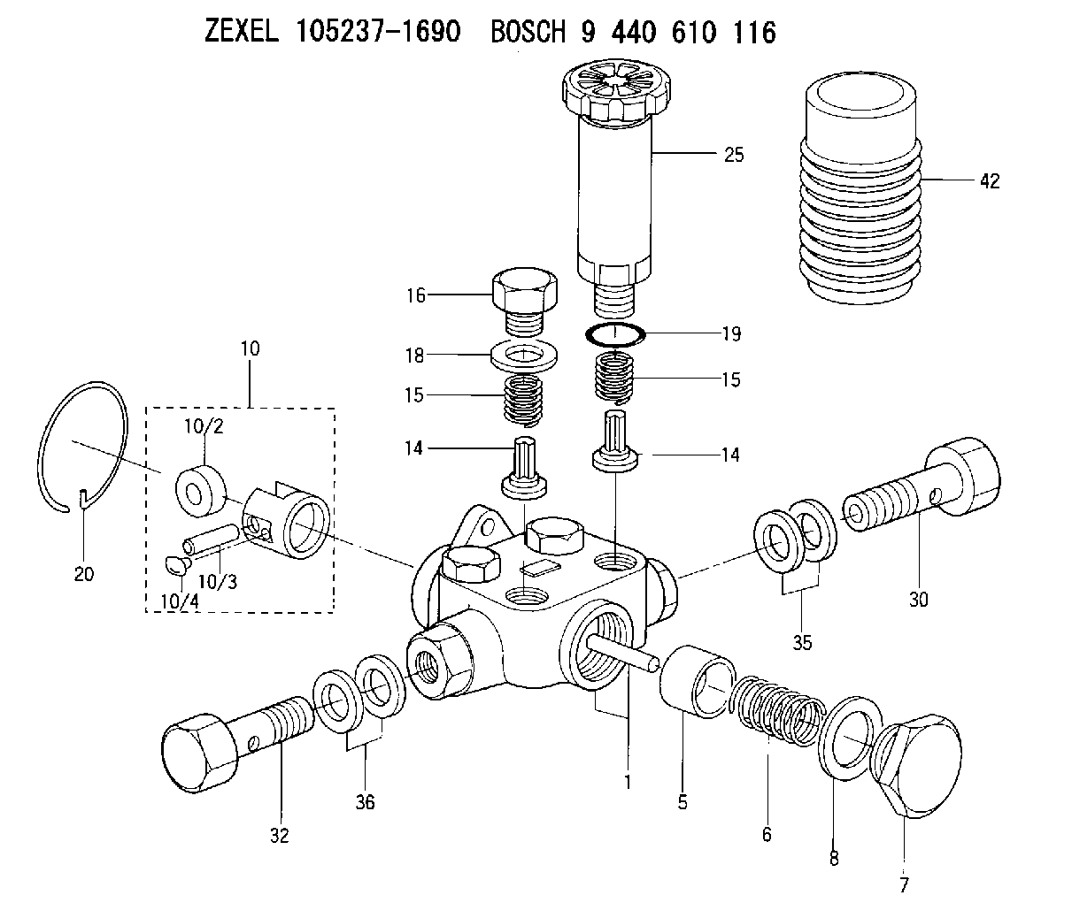
| 1. | [1] | 152004-2320 | PUMP HOUSING |
| 5. | [1] | 152100-1120 | PUMP PLUNGER |
| 6. | [1] | 152102-1300 | COMPRESSION SPRING |
| 7. | [1] | 152105-1500 | CAPSULE |
| 8. | [1] | 029332-6030 | GASKET |
| 10. | [1] | 152111-4420 | TAPPET |
| 10/2. | [1] | 152112-0800 | ROLLER |
| 10/3. | [1] | 152113-1300 | BEARING PIN |
| 10/4. | [2] | 152114-1600 | SLIDER |
| 14. | [4] | 152115-0500 | VALVE BODY |
| 14. | [4] | 152115-0500 | VALVE BODY |
| 15. | [4] | 152116-0200 | COILED SPRING |
| 15. | [4] | 152116-0200 | COILED SPRING |
| 16. | [3] | 152117-0400 | CAPSULE |
| 18. | [3] | 029331-6030 | GASKET |
| 19. | [1] | 029631-6060 | O-RING |
| 20. | [1] | 152121-0400 | LOCKING WASHER |
| 25. | [1] | 152200-5420 | HAND PRIMER |
| 30. | [1] | 152300-5920 | EYE BOLT |
| 32. | [1] | 029731-4680 | EYE BOLT |
| 35. | [2] | 029341-4130 | GASKET D20&13.8T2* |
| 36. | [2] | 029341-4130 | GASKET D20&13.8T2* |
| 42. | [1] | 152320-0100 | COVER |
Include in #1:
106681-4023
as SUPPLY PUMP
Cross reference number
Zexel num
Bosch num
Firm num
Name
Information:
Start By:a. remove timing gear coverb. remove fuel injection pump housing and governor 1. Remove four bolts (2), plate (3) and idler gear (1). 2. If the camshaft is not going to be removed, use Tool (A) to remove camshaft gear (4).
Do not turn the crankshaft with the camshaft gear removed. Damage can be caused to the pistons and valves or both.
3. Remove bolts (5) that hold timing gear plate (6) to the cylinder block.4. Remove timing gear plate (6). 5. Use Tool (B) to remove the bearing from the idler gear. The following steps are for the installation of the timing gears and plate.6. Install a new gasket on the timing gear plate.7. Put timing gear plate (6) in position on the cylinder block and install the bolts that hold the timing gear plate to the cylinder block.8. Heat camshaft gear (4) to a maximum temperature of 205° C (400° F) for no longer than three hours and install it on the camshaft.9. Use Tool (B) and install the bearing in the idler gear. Set the gear on the front face (face with the timing marks). Drive the bearing from the rear face toward the front face of the gear. Install the bearing to a depth of 1.5 0.5 mm (.06 .02 in) below the rear face of the idler gear.10. Install the idler gear, plate and bolts. Be sure No. 1 cylinder is at top center on the compression stroke. Install the idler gear so "V" mark (7) on the idler gear is in alignment with the "V" mark on the crankshaft gear. "K" marks (8) on the camshaft gear can be seen at the outer edges of the idler gear.End By:a. install fuel injection pump housing and governorb. install timing gear cover