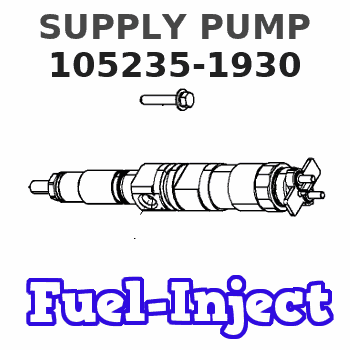
Information supply pump
BOSCH
9 440 610 813
9440610813
ZEXEL
105235-1930
1052351930
Rating:
Scheme ###:
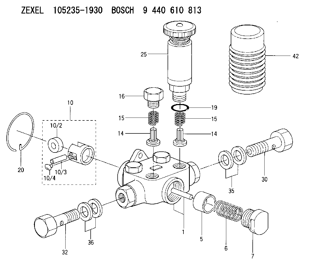
| 1. | [1] | 152002-2020 | PUMP HOUSING |
| 5. | [1] | 152100-1120 | PUMP PLUNGER |
| 6. | [1] | 152104-0500 | COMPRESSION SPRING |
| 7. | [1] | 152105-0400 | CAPSULE |
| 10. | [1] | 152111-4520 | TAPPET |
| 10/2. | [1] | 152112-0900 | ROLLER |
| 10/3. | [1] | 152113-1300 | BEARING PIN |
| 10/4. | [2] | 152114-1600 | SLIDER |
| 14. | [4] | 152115-0500 | VALVE BODY |
| 14. | [4] | 152115-0500 | VALVE BODY |
| 15. | [4] | 152116-0200 | COILED SPRING |
| 15. | [4] | 152116-0200 | COILED SPRING |
| 16. | [3] | 152117-0400 | CAPSULE |
| 19. | [1] | 029631-6060 | O-RING |
| 20. | [1] | 152121-0200 | LOCKING WASHER |
| 25. | [1] | 152200-5320 | HAND PRIMER |
| 30. | [1] | 152300-3620 | EYE BOLT |
| 32. | [1] | 029731-4680 | EYE BOLT |
| 35. | [4] | 029341-4130 | GASKET D20&13.8T2* |
| 36. | [2] | 132400-0200 | ADAPTOR |
| 42. | [1] | 152320-0100 | COVER |
Cross reference number
Zexel num
Bosch num
Firm num
Name
Information:
Governor Linkage Adjustment
(1) Rod. (2) Nut. (3) Control lever. (4) Lever. (5) Pin. (6) High idle stop. (7) Locknut. (8) Low idle stop. (9) Locknut. (10) Decelerator treadle. (11) Floor plate. (12) Accelerator treadle. (13) Lever. (14) Rod. (15) Locknut. (16) Lever. (17) Locknut. (A) 9.7 1.5 mm (.38 .06 in). (B) 4.8 1.5 mm (.19 .06 in). (C) 38.1 1.5 mm (1.50 .06 in). (D) 60.5 3.0 mm (2.38 .12 in).Governor Linkage Adjustment
DO NOT USE control lever (3), or decelerator treadle (10) to shut OFF the engine.To shut engine OFF, pull up on accelerator treadle (12).1. Tighten nut (2) just enough so position of control lever (3) is not affected by the operation of the accelerator treadle (12) and decelerator treadle (10).2. With the parking brake ON and engine stopped, BE SURE disconnect switch is OFF.3. Remove pin (5).4. Loosen LOW IDLE stop (8) and HIGH IDLE stop (6) so they do not touch lever (13).5. Move control lever (3) to LOW IDLE position.6. Turn LOW IDLE stop (8) until it touches lever (13) and tighten locknut (9).7. Adjust length of rod (14) so distance from top of lever (16) to bottom of floor plate (11) is (C) 38.1 1.5 mm (1.50 .06 in) as shown.8. Loosen locknut (15) and adjust length of rod so top of decelerator treadle (10) is (B) 4.8 mm (.19 in) above floor plate (11) as shown. If machine is equipped with a thick floor insulation pad, (used with enclosed cab), adjust decelerator treadle (10) so top of treadle is (A) 9.7 1.5 mm (.38 .06 in) above top of floor plate and tighten locknut (15).9. Move control lever (3) to HIGH IDLE position.10. Turn HIGH IDLE stop (6) until it touches lever (13) and tighten locknut (7).11. Loosen locknut (17) and adjust accelerator treadle (12) so that distance from bottom of plate on treadle to top of floor plate (11) is (D) 60.5 3.0 mm (2.38 .12 in) as shown.12. Move lever (4) to HIGH IDLE position and adjust length of rod (1) so pin (5) can be installed.13. Install pin (5).
DO NOT adjust the linkage so the treadle can be used to shut off the engine. If the operator is in a standing position and places a foot on the treadle, the engine could be unexpectedly shut off, creating a situation where the machine can be difficult to control.
814B, 815B, 816B, 966D
1. Set governor shaft to the off position (approximately 35° right of twelve o'clock) and attach lever (1).2. Adjust cable assembly (2) to within 3 mm (.12 in) of the end of travel and tighten bulkhead (3) nuts to ... 100 15