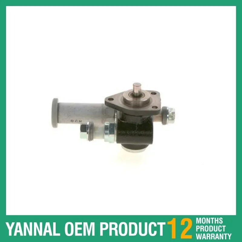
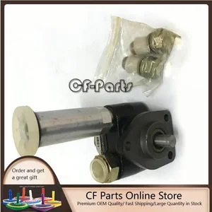
Information supply pump
BOSCH
9 441 610 439
9441610439
ZEXEL
105220-7560
1052207560
ISUZU
8973572640
8973572640

Rating:
Compare Prices: .
As an associate, we earn commssions on qualifying purchases through the links below

Fuel Feed Pump 105220-7560 1052207560 Fits For Isuzu 4BG1 6BG1 Engine
leisurely Package included:Fuel Feed Pump *1 || Feature: Stable characteristics, high reliability. || We offer free repair or return or exchange service in the warranty. || Note: In avoid to order wrong parts, pls first check the PART NO. of the item in your car before buying. || Warm reminder: We will provide comprehensive after-sales service and technical support to ensure that any issues encountered during use can be resolved promptly. Thank you.
leisurely Package included:Fuel Feed Pump *1 || Feature: Stable characteristics, high reliability. || We offer free repair or return or exchange service in the warranty. || Note: In avoid to order wrong parts, pls first check the PART NO. of the item in your car before buying. || Warm reminder: We will provide comprehensive after-sales service and technical support to ensure that any issues encountered during use can be resolved promptly. Thank you.

Fuel Feed Pump 105220-7560 1052207560 Compatible with Isuzu 4BG1 6BG1 Engine
DJCXYSM Product Name:Fuel Feed Pump || Part Number:105220-7560 1052207560 || Application:Compatible with Isuzu 4BG1 6BG1 Engine || NOTE: To avoid unnecessary returns please check the part number before purchasing or tell us the picture of your engine model and nameplate to reduce the error rate. || TIP: If you cannot find the required product part number, please consult us and we will reply as soon as possible.
DJCXYSM Product Name:Fuel Feed Pump || Part Number:105220-7560 1052207560 || Application:Compatible with Isuzu 4BG1 6BG1 Engine || NOTE: To avoid unnecessary returns please check the part number before purchasing or tell us the picture of your engine model and nameplate to reduce the error rate. || TIP: If you cannot find the required product part number, please consult us and we will reply as soon as possible.

Tendparts Fuel Pump Assembly 8973572640 8-97357264-0 Compatible With Hitachi Wheel Loader ZX160W ZX180LC ZX180W LX80-7
Tendparts Part Numbers: 8973572640 8-97357264-0 || Compatible With Hitachi Wheel Loader ZX160W ZX180LC ZX180W LX80-7 ZX130W || Package Includes: 1x Fuel Pump Assembly || Easy to Install. Manufactured to Precise OE Requirements for Perfect Fit. Reliable Performance. || Replacement Parts. As Good as OEM at a Fraction of the Price. Exact Same Performance as Original.
Tendparts Part Numbers: 8973572640 8-97357264-0 || Compatible With Hitachi Wheel Loader ZX160W ZX180LC ZX180W LX80-7 ZX130W || Package Includes: 1x Fuel Pump Assembly || Easy to Install. Manufactured to Precise OE Requirements for Perfect Fit. Reliable Performance. || Replacement Parts. As Good as OEM at a Fraction of the Price. Exact Same Performance as Original.
You can express buy:
USD 174.32
14-06-2025
14-06-2025
Competitive Price Fuel Pre-Supply Pump 9441610439 For ISUZU 1-15750-199-0 8-97357-264-0
USD 97.9
13-05-2025
13-05-2025
Fuel Feed Pump 8973572640 for Hitachi LX80-7 ZX130W ZX130W-AMS ZX160W ZX160W-AMS ZX180LC ZX180LC-AMS ZX180LC-HCME
Images:
USD 360

[28-Sep-2022]
Scheme ###:
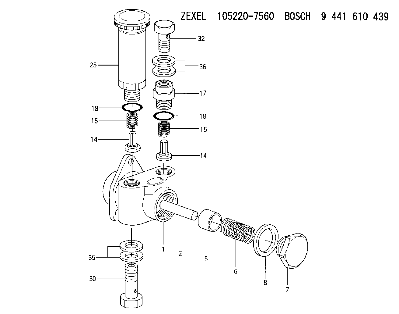
| 1. | [1] | 152062-0120 | PUMP HOUSING |
| 2. | [1] | 152030-0300 | STOP PIN |
| 5. | [1] | 152100-2301 | PUMP PLUNGER |
| 6. | [1] | 152102-2300 | COMPRESSION SPRING |
| 7. | [1] | 152105-1500 | CAPSULE |
| 8. | [1] | 139526-0000 | GASKET |
| 14. | [2] | 152115-0500 | VALVE BODY |
| 14. | [2] | 152115-0500 | VALVE BODY |
| 15. | [2] | 152116-0200 | COILED SPRING |
| 15. | [2] | 152116-0200 | COILED SPRING |
| 17. | [1] | 152118-0900 | ADAPTOR |
| 18. | [2] | 029631-6060 | O-RING |
| 18. | [2] | 029631-6060 | O-RING |
| 25. | [1] | 152200-6721 | HAND PRIMER |
| 30. | [1] | 152300-5620 | EYE BOLT |
| 32. | [1] | 029731-4580 | EYE BOLT |
| 35. | [2] | 029341-4080 | GASKET |
| 36. | [2] | 029341-4080 | GASKET |
Include in #1:
101402-7791
as SUPPLY PUMP
Cross reference number
Zexel num
Bosch num
Firm num
Name
Information:
Cylinder Head And Valve Components
Check cylinder head for cracks before reconditioning.Flatness of the cylinder head should be within .006 in. (0.15 mm) total, and a maximum of .003 in. (0.08 mm) for any 6 in. (152.4 mm) span. A maximum stock removal of .010 in. (0.25 mm) is permissible when resurfacing the head.Always check the thickness of a cylinder head before resurfacing. The cylinder head may have been resurfaced before and would not have enough stock to be resurfaced again.To check the thickness of a cylinder head, measure through the fuel injection nozzle holes at each end of the cylinder head. For the correct thickness of the cylinder head, see the topic CYLINDER HEAD in the SPECIFICATIONS.The exhaust valve seats have replaceable inserts. To remove, use the 8S7170 Valve Seat Insert Puller Group.
REMOVING EXHAUST VALVE SEAT INSERTFreeze the exhaust valve seat inserts or use the 8S7170 Valve Seat Insert Puller Group to install inserts into head. Be sure bores are clean, free of burrs, and the insert has a good press fit into the bore.After inserts are installed, grind the seat face of the insert to be sure it is flat, has the correct angle, and is in alignment with the bore in the valve guide. For specifications, see VALVE GRINDING SPECIFICATIONS CHART. Replace exhaust valve seat inserts when valve seat width or valve head-to-cylinder head face can not be machined to the correct specification. For specifications, see VALVE GRINDING SPECIFICATIONS CHART.A 2N8943 Valve Seat Insert for the intake valve is available. This insert can be used in the repair of cylinder heads which have an intake valve seat with damage. Before, damage to an intake valve seat made replacement of the cylinder head assembly necessary.To use a 2N8943 Valve Seat Insert, the inlet port of the cylinder head must be machined to a diameter of 2.1470 .0005 in. (54.534 0.013 mm) and to a depth of .442 .002 in. (11.23 0.05 mm).To install a 2N8943 Valve Seat Insert into the cylinder head, freeze the insert or use a 2P2343 Extractor with the 8S7170 Valve Seat Insert Puller Group. After an insert is installed, grind the seat face of the insert to be sure it is flat, has the correct angle, and is in alignment with the bore in the valve guide. For specifications, see VALVE GRINDING SPECIFICATIONS CHART.Clean valve guides of all carbon and oil, using the 5P5176 Brush and a solvent.The valve guides are cast in the cylinder heads. Check each valve guide bore size 3/4 in. (19.1 mm) deep from each end. The bore size is .3745 .0005 in. (9.512 0.013 mm) and the maximum size worn is .3760 in. (9.550 mm). Valve guides worn more than the maximum wear size, can be restored to original tolerances through knurling.Use the 5P3536 Valve Guide Gauge Group to check the bore of the valve guides. Special Instructions GMG02562 gives complete and detailed instructions for use of the 5P3536 Valve Guide Gauge