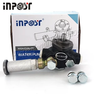
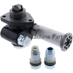
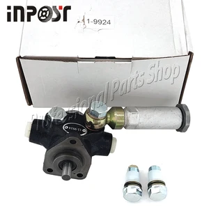
Information supply pump
BOSCH
9 440 610 118
9440610118
ZEXEL
105220-5571
1052205571
KUBOTA
1901352022
1901352022

Rating:
Compare Prices: .
As an associate, we earn commssions on qualifying purchases through the links below

Feed Fuel Pump 105220-5571 11-9924 25-38666-00 for Zexel for Isuzu C201 Engine Thermo King for Carrier CT 4.134 Ultra/Vector
LUNIUBIQING Applications: for Zexel || Applications: for Isuzu C201 Engine Thermo King || Applications: for Carrier CT 4. 134, CT 4.134 || Applications: for Carrier Vector 1950 / 1850MT / 1850 / 1800TM / 1500 ULTRA
LUNIUBIQING Applications: for Zexel || Applications: for Isuzu C201 Engine Thermo King || Applications: for Carrier CT 4. 134, CT 4.134 || Applications: for Carrier Vector 1950 / 1850MT / 1850 / 1800TM / 1500 ULTRA

Replacement Parts FOR Fuel Supply Pump for Zexel 105220-5571 1052205571 KUBOTA: 19013-52022 Mod-JN88-2004
Generic ✔ Reliable Engine Starting – Ensures consistent power delivery to the starter motor for quick, efficient starts across various equipment types and conditions. || ✔ Built for Heavy-Duty Use – Designed to handle high-current loads, vibration, and harsh environments typical of tractors, mowers, and utility vehicles. || ✔ Wide Brand Compatibility – Fits a variety of models from top brands like For Ford New Holland, John Deere, Kubota, Caterpillar (Cat), Husqvarna, E-Z-GO, and more. || ✔ Direct OEM-Style Replacement – Matches factory specifications for a secure fit and trouble-free installation—no modifications required. || ✔ Ideal for Tractors, Mowers & Utility Vehicles – Perfect for restoring function to farm equipment, garden tractors, golf carts, and more.
Generic ✔ Reliable Engine Starting – Ensures consistent power delivery to the starter motor for quick, efficient starts across various equipment types and conditions. || ✔ Built for Heavy-Duty Use – Designed to handle high-current loads, vibration, and harsh environments typical of tractors, mowers, and utility vehicles. || ✔ Wide Brand Compatibility – Fits a variety of models from top brands like For Ford New Holland, John Deere, Kubota, Caterpillar (Cat), Husqvarna, E-Z-GO, and more. || ✔ Direct OEM-Style Replacement – Matches factory specifications for a secure fit and trouble-free installation—no modifications required. || ✔ Ideal for Tractors, Mowers & Utility Vehicles – Perfect for restoring function to farm equipment, garden tractors, golf carts, and more.

You can express buy:
USD 33.39
14-06-2025
14-06-2025
11-9924 Fuel Pump For Isuzu C201 Thermo King Vector ULTRA Sentry Super SB I-III 105220-5571 119924
USD 56.64
01-07-2025
01-07-2025
Fuel Pump For 25-38666-00 Thermo King Isuzu C201 Engine ZEXEL 105220-5571
USD 33.39
25-05-2025
25-05-2025
11-9924 New Fuel Pump 119924 for Thermo King Isuzu C201 Engine Zexel 105220-5571
Images:
USD 33.39

[28-Apr-2025]
USD 65

[28-Apr-2025]
Cross reference number
Zexel num
Bosch num
Firm num
Name
Information:
Problem
The retainer clips for the fuel injectors may crack or break on certain Challenger 75 Tractors. Also, the unit injector rocker arms may crack.
Affected Product
Mode & Identification Number
CH75 (4CJ1-308, 4CJ311-317, 4CJ320-331, 4CJ350, 4CJ356,4CJ375-378, 4CJ380, 4CJ382, 4CJ383, 4CJ386, 4CJ391, 4CJ394, 4CJ396, 4CJ406)
Parts Needed
6 - 7E8872 Rocker Arm Assembly (Use as needed)6 - 6I2538 Clip6 - 0R3398 Injector Group (Use as needed)Action Required
See attached rework procedure.
Service Claim Allowances
If required, add the following:
0.5 Hr R&I first fuel injector0.4 Hr R&I each additional fuel injectorParts Disposition
Handle the parts in accordance with your Warranty Bulletin on warranty parts handling.
Attach.
(1-Rework Procedure)Rework Procedure
1. Check for 3X stamped on the block next to the serial number plate. If the block has been stamped do not proceed with the rework unless suspect injectors have recently been installed in that engine. Check SIMS history to be sure.2. Remove hood from over engine, valve covers, and rocker arm stands.3. Inspect the injector rocker arms for the heat code and die code as shown in Illustration 1. Replace any injector rocker arms that have both heat code "1" and die code "1*C" (* Note symbol in Illustration.)
Illustration 1 - Injector Rocker Arm Identification Injector rocker arms must have BOTH heat code "1" and die code "1*C" to be eligible for replacement.
4. Inspect unit injectors for a paint strip across the top face of the spring retainer (either yellow or red). A paint stripe indicates the unit injector has been reworked previously.5. Remove the return to tank fuel line at the fuel manifold adapter (siphon break) and install a 0-100 psi gauge at the manifold.6. Use an O-ring pick to remove the O-ring from the spring retainer of each injector to be reworked. Remove the rocker arm thrust pad from each injector.7. Pressurize fuel system using the priming pump to 30 psi and maintain pressure from 15-30 psi during rework (fuel pressure keeps the injector plunger extended during clip replacement).8. Inspect the 9U5300 Unit Injector Spring Compressor Group. See Illustration 2. The 9U5320 Fixture is for off engine use only.
Illustration 2 - 9U5300 Unit Injector Spring Compressor GroupInstall the compressor group into a rocker arm support bolt hole with the arm aligned over a unit injector spring. Be sure the 5P0541 Nut is backed off to the top of the 9U5321 Tube before tightening the 7X0909 Bolt.
Install the compressor at hole locations closest to the inlet valves.Tighten the 5P0541 Nut to compress the injector spring only enough to allow removal of the clip (the clip is like a valve keeper).
9. Use a small magnet (pencil size works best) and a suitable clip removal tool to remove the old clip from the injector. Do not release tension on the spring until a new clip is installed. Releasing tension before a new clip is installed will cause the injector will come apart. See Illustration 3.
Illustration 3 - Use caution when handling injectors with missing clips. Loose springs and retainers will allow ball to come loose and fall into the engine.10. Inspect the clip