Information supply pump
BOSCH
9 440 610 748
9440610748
ZEXEL
105220-5390
1052205390
Rating:
Scheme ###:
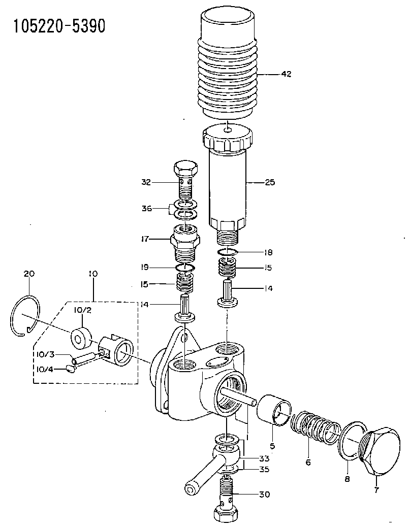
| 1. | [1] | 152003-1020 | PUMP HOUSING |
| 5. | [1] | 152100-1120 | PUMP PLUNGER |
| 6. | [1] | 152102-1600 | COMPRESSION SPRING |
| 7. | [1] | 152105-1500 | CAPSULE |
| 8. | [1] | 029332-6030 | GASKET |
| 10. | [1] | 152111-2820 | TAPPET |
| 10/2. | [1] | 152112-0100 | ROLLER |
| 10/3. | [1] | 152113-0700 | BEARING PIN |
| 10/4. | [2] | 152114-0400 | SLIDER |
| 14. | [2] | 152115-0500 | VALVE BODY |
| 14. | [2] | 152115-0500 | VALVE BODY |
| 15. | [2] | 152116-0200 | COILED SPRING |
| 15. | [2] | 152116-0200 | COILED SPRING |
| 17. | [1] | 152118-0900 | ADAPTOR |
| 18. | [1] | 029631-6060 | O-RING |
| 19. | [1] | 029631-6060 | O-RING |
| 20. | [1] | 152121-0200 | LOCKING WASHER |
| 25. | [1] | 152200-5420 | HAND PRIMER |
| 30. | [1] | 152300-5920 | EYE BOLT |
| 32. | [1] | 029731-4680 | EYE BOLT |
| 33. | [1] | 139814-0600 | INLET UNION |
| 35. | [2] | 029341-4130 | GASKET D20&13.8T2* |
| 36. | [2] | 029341-4130 | GASKET D20&13.8T2* |
| 42. | [1] | 152320-0100 | COVER |
Include in #1:
101452-3020
as SUPPLY PUMP
Cross reference number
Zexel num
Bosch num
Firm num
Name
Information:
6. Coat the seal of the element with a thin film of clean engine oil or antifreeze. 7. Install the element. Tighten it until the seal contacts the base, then tighten it an additional 3/4 turn. 8. Open the inlet valve and the outlet valve. 9. Maintain the coolant level above the low level plate. 10. Clean and install the radiator cap.11. Start the engine and check for leaks.Brakes
Inspect - Adjust
The machine must be level, the bowl lowered, and the parking brake applied.1. Block the wheels securely.2. Start the engine. 3. When the air pressure reaches the NORMAL range, stop the engine. 4. Release the parking/emergency brake. 5. Measure the distance from the rotochamber to the slack adjuster clevis retaining pin. 6. Apply the service brake and measure the amount of travel of the rod. If the travel is 76 mm (3 inches) or more, adjust the brake.7. Measure the brake rotochamber rod travel of all four wheel brakes. Scraper rotochambers are located inside the push frame.To Adjust
1. Loosen the adjustment locking bolt. 2. Turn the adjusting bolt, as required, until the travel is 41 mm (1.62 inches). 3. Tighten the locking bolt. 4. Apply and release the brakes, watching the rotochamber rod for binding.5. Observe the diaphragm for leaks. 6. Start the engine and allow air pressure to reach 690 kPa (100 psi) or in the green range on the air pressure gauge.7. Apply the parking brake.8. Stop the engine.9. Remove the blocking from the wheels.Check the Air System for Leaks
1. Start the engine and allow air pressure to reach 690 kPa (100 psi) or in the green range on the air pressure gauge. 2. Apply the service brakes and hold them in the applied condition.3. Stop the engine.4. With the brakes applied, watch the air pressure gauge.5. The pressure should drop no more than 35 kPa (5 psi) in 10 minutes.6. If the air pressure loss is greater than 35 kPa (5 psi), inspect the air lines and connections. Make any necessary repairs.To Test Brakes
Be sure the area around the vehicle is clear of personnel and obstructions.Fasten the seat belt before operating the vehicle.Test the brakes on a dry, level surface.
The vehicle must be on a dry, level surface, the bowl lowered and the parking brake applied.The following tests are to determine if the service brake or parking/emergency brake is functional. These tests are not intended to measure maximum brake holding effort.Brake holding effort required to hold a vehicle at a specific engine rpm will vary from vehicle to vehicle due to differences in engine setting, power train efficiency, etc., as well as differences in brake holding ability.Engine rpm at beginning of vehicle movement, with service or parking/emergency brake applied, should be compared against the engine rpm your specific vehicle was able to hold on a prior test, as an indication of system deterioration.Service Brake
1. Start the engine. Allow the engine to reach the normal operating temperature.2. When air pressure registers 690 kPa (100 psi) or